


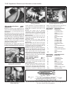
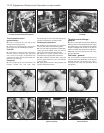
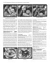
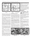
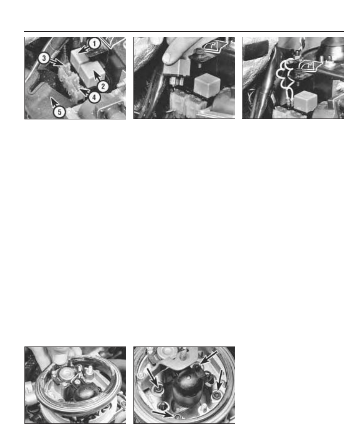
26 Loosen off the knurled retaining nut and
remove the cover from the fuel pump relay.
This is located on the left-hand suspension
turret in the engine compartment (photo).
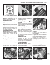
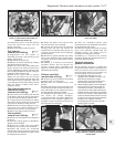
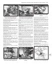
27 Carefully pull free the fuel pump relay,
then start the engine and run it until it stops
(photo). The fuel system is now
depressurised. Turn the ignition off before
removing/dismantling any components.
28 Do not refit the fuel pump relay or turn the
ignition on until the system is fully
reconnected. When the engine is ready to be
restarted, refit the relay and its cover, then
restart the engine in the normal manner.
Fuel pump and supply
system checks ∞
29 Specialised equipment is required to
undertake accurate tests in the fuel supply
system and such checks must therefore be
entrusted to a FIAT dealer or a fuel injection
specialist. If the fuel pump is suspected of
malfunction, a basic check can be made by
removing the fuel filler cap then listening
through the filler pipe, get an assistant to turn
on the ignition whilst you listen to hear if the
pump is heard to operate in the tank. If the
pump fails to operate, check that the pump
fuse is sound and that its connection (and
also that of the relay) are clean and secure.
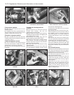
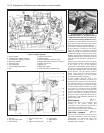
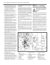
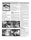
30 The pump can be further checked by first
depressurising the fuel system as described in
the previous sub-Section, then disconnect the
fuel supply pipe at the injector unit and locate
it in a suitable container. With the fuel pump
relay removed, connect up a suitable test lead
with a 7.5 amp (10 amp on models with
catalyst) fuse, in series, to the relay terminals
30 and 87, and check that fuel flows into the
container from the supply pipe (photo). If a
suitable pressure gauge is available for
connecting into the fuel line between the
engine compartment fuel filter and the
injection unit, check that the fuel pressure is
as specified at the beginning of this Chapter.
31 If the pump fails to operate, check that the
battery is in good condition and that the pump
wiring connections are clean and secure
before condemning the pump. To remove the
pump unit from the fuel tank, proceed as
described in the following sub-Section.
Fuel pump -
removal and refitting ¡
32 Release the pressure from the fuel system
as described previously.
33 Move the front seats forward, then tilt the
rear seat cushions forward. Peel back the
luggage area floor cover from the right-hand
side towards the centre to expose the access
cover above the pump/sender unit in the floor.
Remove the access cover.
34 Detach the wiring connectors from the
pump unit and the fuel level sender unit.
35 Loosen off the hose retaining clips and
detach the fuel supply and return hoses from
the pump unit connections. Mark the hoses
for identity to avoid incorrect attachment
during refitting.
36 Unscrew the retaining nuts then carefully
lift out and withdraw the fuel pump/level
sender unit from the fuel tank.
37 Refitting is a reversal of the removal
procedure. A new seal gasket must be used
and it is important to ensure that all
connections are securely and correctly made.
Injector unit -
removal and refitting ¡
38 Depressurise the fuel system as
described previously, then disconnect the
battery negative lead.
39 Remove the air cleaner unit and the
rubber seal (photo).
40 Disconnect the engine idle speed check
actuator lead and the throttle position switch
lead from the side faces of the injector unit.
41 Undo the retaining clips and detach the
fuel supply and return hose from the injector
unit. If crimped type retaining clips are fitted,
they will have to be carefully cut free and new
screw type clips obtained to replace them.
Take care not to cut into the hoses when
releasing the crimped type clips.
42 Detach the crankcase ventilation hose
from the fuel injector unit.
43 Disconnect the accelerator linkage at the
throttle lever on the injector unit.
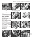
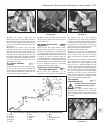
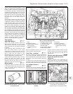
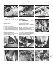
44 Undo the four retaining screws and lift the
injector unit from the inlet manifold. Remove
the gasket (photo).
45 Clean the injector unit and the inlet
manifold mating faces.
46 Refit in the reverse order of removal.
Intake air temperature
sensor - removal and
refitting ¡
47 The air temperature sensor is located in
the top of the injector unit. It is basically a
resistor which varies its value in accordance
with the air temperature entering the induction
circuit from the air filter. The sensor can then
transmit the registered air temperature at this
point to the ECU temperature sensor (2).
48 Remove the air cleaner unit and its
mounting bracket in the injector.
49 Disconnect the wiring connector from the
13•76 Supplement: Revisions and information on later models
9D.44 Injector unit retaining screws
(arrowed)
9D.39 Removing the filter seal from the
injector unit
9D.30 Test lead connected to relay
terminals 30 and 87
9D.27 Fuel pump relay removal
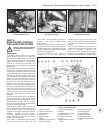
9D.26 Fuel pump relay (1), injection control
relay (2), Lambda sensor fuse (3) and pump
fuse (4) with cover (5) removed