


DATA LINK TO GTI UNITS LBI-3907
7
33
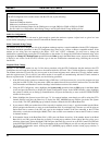
GTI UnitGTI Configurator
11
22
33
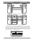
D-Sub 9-Pin (F)
Gnd
Tx Data
Rx Data
D-Sub 9-Pin (M)
Signal Ground
Rx Data
Tx Data
COM Port RS-232 Port
50 Feet Max
PC Monitor Extension Cable
4
5
6
7
8
9
DTR
CTS
RTS
4
5
6
7
8
9
DTR
RTS
CTS
9-Pin (F) 9-Pin (M)
D-SubD-Sub
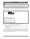
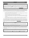
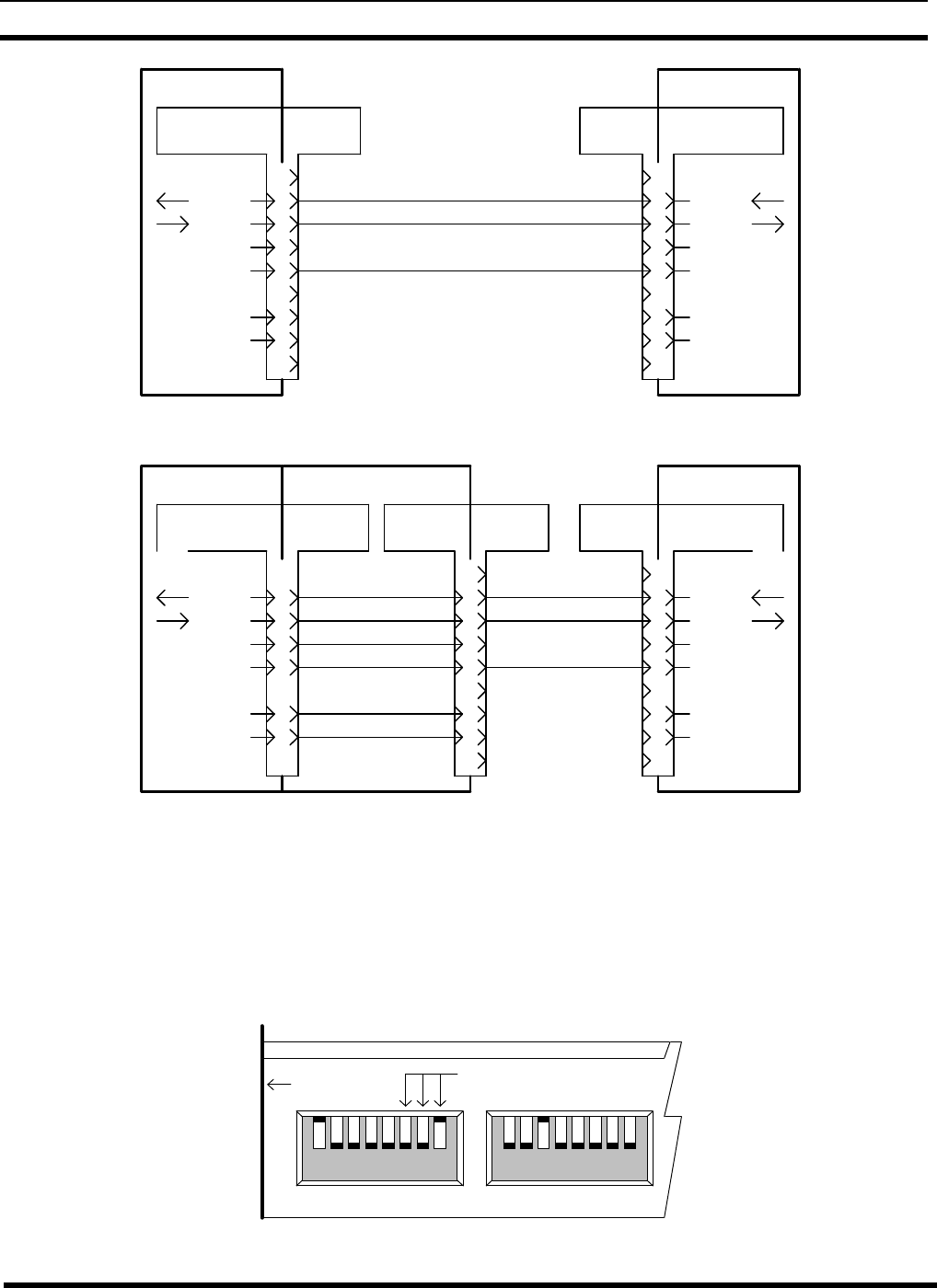
Figure 23 - Communication Setup for Local Data Link (9-Pin COM Port)
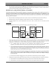
GTI UnitGTI Configurator
1
2
2
3
3
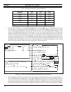
D-Sub 9-Pin (F)
Gnd
Tx Data
Rx Data
D-Sub 25-Pin (M)
Signal Ground
Rx Data
Tx Data
COM Port RS-232 Port
50 Feet Max
PC Monitor Extension Cable
4
5
6
7
8
9
DTR
CTS
RTS
20
7
4
5
DTR
RTS
CTS
25-Pin (F) 9-Pin (M)
1
2
3
9-Pin (M)
4
5
6
7
8
9
9-Pin (F)
Adapter
D-SubD-Sub D-Sub D-Sub
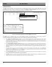
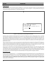
Figure 24 - Communication Setup for Local Data link (25-Pin COM Port)
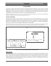
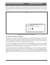
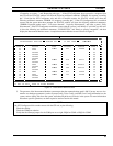
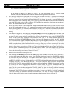
2. Set the baud rate for the RS-232 port on the GTI unit using DIP switch SW2 sections 6, 7, and 8 located on the right
side of the GTI unit. To get to the DIP switch after the GTI unit has been mounted in an EDACS repeater cabinet,
remove four screws in front and two in back. Then slide the GTI unit forward just enough to reach the DIP switch. If
there is enough slack in the connecting cables, it isn’t necessary to disconnect them or power from the GTI unit. The
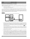
layout of the DIP switch sections is shown in Figure 25. The DIP switch settings for various baud rates are shown in
Table 4. The recommended baud rate is 9600 bps. After you have set the DIP switch sections, press the RESET
button on the GTI unit to force it to read the new DIP switch settings.
18
18
SW2 SW1
FRONT PANEL
1
00
1
SECTIONS SET BAUD RATE
RIGHT SIDE VIEW OF GTI UNIT
Figure 25 - Location of DIP Switch Sections