


Page 6 of 44
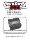
Catalog #91001, 91003, 91004, 91005, 91007, 91009
Rev. 2/06 - RS/mc
©2006 Edelbrock Corporation
Brochure #63-0282
Connection To Battery Power
Power is connected to the QwikData box using the red and black wires on the wiring harness. Connect the red wire to a switched 12V
source (e.g. output of ignition switch) and the black wire to a good ground. The recommended grounding point for most installations
is the ground bolt located on the back of the right side cylinder head. The black wire in the wiring harness is supplied with a terminal
to fit this grounding bolt. Do not connect the red wire directly to the battery, as this will put an unnecessary current draw on your
battery (approximately 250 ma) when the ignition switch is off. QwikData does not need continual battery to preserve data and
configuration settings.
Note: A good system ground is very important for proper operation of the QwikData system. Whenever possible, connect the ground
as described above. It is also very important to have a good ground strap between the engine and the chassis.
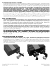
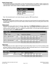
Engine RPM Connection
Two un-terminated wires are provided on the main harness for RPM input. Most electronic ignition systems provide a tach output and
these wires should be connected directly to this output. The purple wire should be connected to the tach signal (+) and the black wire
should be connected to a good ground or (-) signal terminal if provided by the ignition system.
WARNING!!!: THIS INPUT SHOULD NOT BE CONNECTED DIRECTLY TO THE IGNITION COIL.
NOTE: The RPM input is calibrated for a typical 8 cylinder application in the default setup but this may require
calibration depending on the installation, (see Reference manual on the QwikData CD ROM for details).
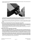
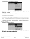
Data Logging On/Off Switch
With the QwikData system, data logging can be started and stopped either automatically based on sensor values or manually with a
switch (default configuration). If manual-logging control is desired, a single pole on/off toggle switch must be installed in the vehicle
and connected to the two logging control wires (yellow and black) labeled “LOG ON/OFF” in the main wiring harness. One wire should
be connected to each terminal on the toggle switch. Data logging will start when the toggle switch is turned on (connecting the black
and yellow wires together) and stop when the switch is turned off. If automatic data logging is used, these wires are not needed.
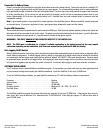
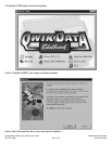
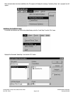
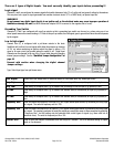
SOFTWARE INSTALLATION
The PC software utilizes a standard Windows installation program. As a precaution, you should shut down any other applications that
may be currently running before starting the QwikData installation. Insert the QwikData CD into your CD-ROM drive.
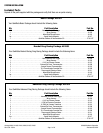
To run the QwikData analysis software, you must install the software on a PC with the following minimum requirements:
Processor: . . . . . . . . . . . . . . . . . . . . . . . . . . . . . . . . . . . . . . . . . .Pentium
System Speed: . . . . . . . . . . . . . . . . . . . . . . . . . . . . . . . . . . . . . .166 mHz
Memory: . . . . . . . . . . . . . . . . . . . . . . . . . . . . . . . . . . . . . . . . . . .32 MB RAM
Operating System: . . . . . . . . . . . . . . . . . . . . . . . . . . . . . . . . . . . .Windows 95 / 98 / 2000 / XP / NT 4.0
Free Disk Space: . . . . . . . . . . . . . . . . . . . . . . . . . . . . . . . . . . . . .16 MB
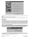
The QwikData installation program should auto-start when you insert the CD into your CD ROM drive. If the program does not auto-
start, select “Run” from the Windows “File” menu and enter "D:\AUTORUN.EXE" in the dialog box (replace “D” with the drive letter of
your CD-ROM drive).