


Page 11 of 44
Catalog #91001, 91003, 91004, 91005, 91007, 91009
Rev. 2/06 - RS/mc
©2006 Edelbrock Corporation
Brochure #63-0282
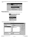
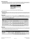
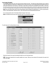
Digital Channel Setup
This menu selection allows you to select whether or not each of the digital channels is to be enabled for viewing or logging, and to
enter in descriptive and calibration information for each channel. For each channel that you intend to use, click the “Channel” Box to
enable that channel. Until the channel is enabled, no additional information can be entered for that channel.
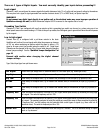
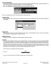
Name: Enter a descriptive name for each channel (will appear on graph) e.g. RPM.Choosing Channels
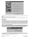
Choosing Channels
While QwikData offers tremendous flexibility by allowing you to configure each channel individually, the standard QwikData packages
are provided pre-configured and you will not need to modify the channel selections unless you are adding optional sensors to the
standard package.
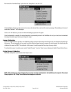
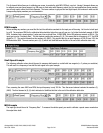
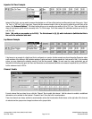
Analog Inputs
Analog Inputs can measure signals in the 0-10 volt range. Voltages above 10V (24 Absolute maximum) will be displayed as 10V.
Channel 16 , will read voltages up to 20V via a 2: I Voltage Divider. Factory settings configure your unit with Channels 9 and 10 to
reading the internal accelerometers, Channel 16 is configured to read battery voltage. If you do not want to take these readings and
require the extra channels, see the jumper page #43.
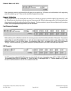
Digital lnputs
These are inputs that can measure a digital (on/off) signal. As well as strictly reading if a signal is on or off (such as monitoring a brake
light switch), QwikData can measure the frequency of a signal (Tach. output or wheel speed sensor), the on or off period (fuel injector
pulse), or count the number of times a signal goes from on to off (or off to on).