


Page 5 of 44
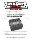
Catalog #91001, 91003, 91004, 91005, 91007, 91009
Rev. 2/06 - RS/mc
©2006 Edelbrock Corporation
Brochure #63-0282
To make installation as easy as possible, the wiring harness provided is completely assembled with connectors that mate to the
supplied sensors. Each sensor is connected to the QwikData unit by simply mating the appropriate connectors. (Refer to the QwikData
Reference Manual on the CD ROM for a description of the wiring harness and the sensor connections.)
Route the wiring harness as needed to make connections to the installed sensors. To connect the circular connectors on the wiring
harness to the sensors, push the mating connectors firmly together and then turn the locking ring clockwise to lock the connectors
together.
Bracket Drag and Import/Compact Drag Racing Package Sensor Connections
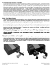
Connect the TK4 Thermocouple Converter box to the harness connector labeled “THERM CONV”. The TK-4 Thermocouple Converter
box is a four-channel unit, with the channels labeled A through D. The EGT Thermocouples then plug into the TK-4 Converter box. By
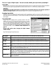
default, the EGT connected to channel A of the TK-4 Converter box is labeled as EGT 1 in the software and so on. You can easily change
the channel’s names using the QwikData software to match the correct cylinder numbers for your installation.
Connect the shaft speed sensor located on the drive shaft to the connector labeled “SPEED”, the connector marked “FUEL PRESS” to
the fuel pressure sensor, etc.
Advanced Drag Racing Package Sensor Connections
Connect the harness connector marked “THERM CONV 1” to the connector on the side of the TK-4 Thermocouple Converter unit #1,
the harness connector marked “THERM CONV 2” to the connector on the side of the TK-4 Thermocouple Converter unit #2, the harness
connector marked “THERM CONV 3” to the connector on the side of the TK-4 Thermocouple Converter unit #3. The TK-4 Thermocouple
Converter box is a four channel unit, with the channels labeled A through D. The EGT Thermocouples then plug into the TK-4 Converter
box. By default, the EGT connected to channel A of the #1 TK-4 Converter box is labeled as EGT 1 in the software and so on up to
channel D of the #2 TK-4 Converter box which corresponds to EGT 8. You can easily change the channel’s names using the QwikData
software to match the correct cylinder numbers for your installation. Channels A and B of TK-4 Converter box #3 are labeled as Water
Temperature and Oil Temperature but can be used to measure any temperatures you want. Connect the shaft speed sensor located
on the input shaft to the connector labeled “Speed 1”, the shaft speed sensor located on the output shaft to the connector labeled
“Speed 2”, the connector marked fuel press, to the fuel pressure sensor, etc.
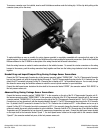
To remove a connector once it is installed, insert a small flat blade screwdriver under the locking clip. Lift the clip while pulling on the
connector (never pull on the wires).