


2001 Edelbrock Corporation
Brochure No. 63-0020
©
Rev. 10/01
Page 23 of 27
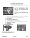
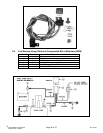
3.12 Knock Sensor By-Pass Relay Installation (Continued)
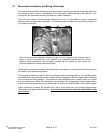
The wire harness attached to the relay includes 4 feet of color-coded wires to make the electrical system
installation for your Edelbrock Nitrous System as easy as possible. We recommend that you do not cut
any lengths of wires from the wire harness or complete the wiring of the nitrous system until all of the
mechanical components are securely mounted in their permanent locations. Do not exceed the 4 feet of
wire to the ECM and the knock sensor, this could send a faulty signal and the system would not work at
optimal power. You can extend the white and black wires beyond the 4 feet if necessary.
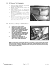
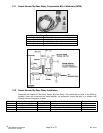
Once all of the system components have been mounted, route the un-cut wires from the harness to each
location allowing enough wire length on each circuit to not interfere with operating linkages, heat sources,
brackets, etc. Pay particular attention to sharp edges along the route of your wire harness as they can
chafe the wires and cause your system to fail.
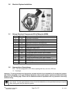
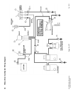
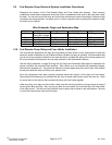
After you have accounted for the routing of your wires, follow the Knock Sensor By-Pass Relay Wiring
Schematic on page 22 and use the Wire Schematic Origin and Destination Map as a guide for which
electrical connectors are used in each circuit. Note that the one wire from the ECM to the Knock Sensor
needs to be cut and intercepted with the relay. This wire is located on the BLUE terminal in pin location
#22. It is a blue wire. Try to keep the Knock Sensor By-Pass Relay as close to this wire as possible.
Once you have decided the location of the relay, secure them with fasteners (not included with kit) such
as sheet metal screws, bolts and nuts, etc.
3.13 Final Electrical Installation Recommendations
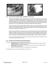
At this time, it is advised that you double-check the following areas:
1. Double-check all wires so that they do not come in contact with any heat sources like exhaust
manifolds, and EGR crossovers to name a few.
2. Double-check the wires that lead from the microswitch to ensure they do not interfere with the
operation of the throttle linkage.
3. Make sure the relay and the fuse are serviceable and mounted securely.
You are ready to hook up your battery and prepare your vehicle to run.