


2001 Edelbrock Corporation
Brochure No. 63-0020
©
Rev. 10/01
Page 11 of 27
2.5 Nitrous Feed Line Mounting
1. Determine the route your main nitrous feed line will follow. Ensure the path does not route the
nitrous feed line too close to the exhaust system, suspension, electrical lines/components or
tires.
2. Attach nitrous supply line to bottle.
3. Feed nitrous line along proposed route.
4. Secure nitrous supply line to underside of vehicle.
Note: Stainless steel covering of the main nitrous feed line is very abrasive. Shield painted
components or sensitive system components like electrical, fuel lines, brake lines or suspension
components to prevent them from contacting main feed line. Rubber hose can be slid over and
retained as a chafe guard.
5. Leave nitrous line loose pending installation of nitrous solenoid.
2.6 Solenoid Mounting
Use the following procedures to install the Performer nitrous solenoids:
Note: Remember to use T
eflon paste only on pipe threads. Do not use Teflon tape.
Hint: Placement of the solenoid is often limited by the lack of possible mounting locations in the
engine compartment. However, if possible, observe the following suggestions:
Solenoid Safety Information
1. Keep solenoid and lines away from exhaust components.
2. Trial fit the solenoids with all lines attached to ensure a proper fit.
3. Solenoids may be mounted sideways or upside-down, if necessary.
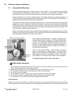
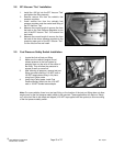
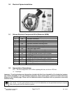
2.6.1 Preparing To Mount Your Solenoids
1. Locate the EFI solenoid bracket, solenoid “tee”, and solenoid mounting screws.
2. This solenoid bracket can be modified (bent, twisted and/or cut) to allow for easier
installation in areas with minimal clearance . Please look at the photo on the next page of
a typical solenoid mounting location, and adapt your bracket according to the needs of your
particular application.
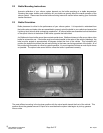
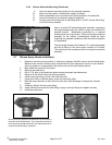
2.6.2 Nitrous Solenoids Mounting
1. Hold one of the nitrous solenoids securely (like in a bench vise) being careful not to harm
the solenoid or block the inlet or outlet port of the solenoid.
2. Install nitrous filter fitting (Blue fitting 4AN X 1/8 NPT) using liquid Teflon, in the inlet port of
the nitrous solenoid.
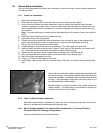
3. Install one of the 1/8 NPT male sides of solenoid “tee”, using liquid Teflon, on the outlet port
of the nitrous solenoid. The female port of solenoid “tee” should be facing outward.
4. Install the remaining 1/8 NPT male end of the solenoid “tee”, using liquid Teflon, into the
inlet port of the second nitrous solenoid. Rotate second solenoid so that it parallels the first.
5. Install the 3AN x 1/8 NPT (blue straight fitting) into the outlet port of second nitrous
solenoid.
6. Install one end of the 1/8 NPT male x 1/8 NPT male nipple fitting, using liquid Teflon, into
nitrous pressure regulator inlet port. This is the port at the end of the regulator.
7. Loosely thread nitrous pressure regulator/nipple assembly into 1/8 NPT female port on
solenoid “tee”.
8. Using liquid Teflon, install 1/8 NPT x 3/16” barb fitting into nitrous pressure regulator.