2001 Edelbrock Corporation
Brochure No. 63-0020
©
Rev. 10/01
Page 19 of 27
3.7 Microswitch Installation and Wiring (Continued)
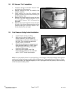
The bolts used to attach the microswitch have extra length to allow for spacing the microswitch away from
the bracket to offer a level of adjustability of the microswitch. After determining the position of the
microswitch, we recommend trimming the bolts for a clean installation.
Due to the wide variety of throttle linkage combinations in use, it is impossible to supply a microswitch
bracket custom-tailored to each application. The universal bracket-supplied will need to be modified to fit
your specific application.
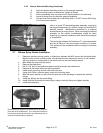
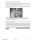
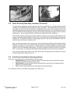
Here is the microswitch assembly mounted for use. It is an example of one of many ways in
which to mount a microswitch on your manifold. The microswitch bracket allows for many
different mounting positions. The microswitch bracket can be modified to clear almost any
potential interference around the throttle linkage.
Please look for potential microswitch mounting locations and adapt your microswitch bracket according to
the needs of your particular application.
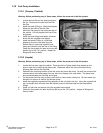
The microswitch bracket is drilled to allow many different switch mounting positions. This flexibility allows
the microswitch to be positioned in such a manner that it will engage the throttle linkage without interfering
with its normal and safe operation. The bracket may be manipulated (bent, twisted, and/or cut) to best
suit your combination. Mount the microswitch so the actuation arm is triggered by throttle linkage making
sure all wiring and the bracket do not interfere with the smooth and safe operation of the throttle linkage.
Adjust microswitch to ensure the actuation arm “clicks” at the same point your throttle linkage reaches
wide open throttle against the throttle stop. At no time should the microswitch be enabled before wide
open throttle.


