


2001 Edelbrock Corporation
Brochure No. 63-0020
©
Rev. 10/01
Page 22 of 27
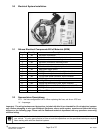
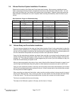
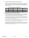
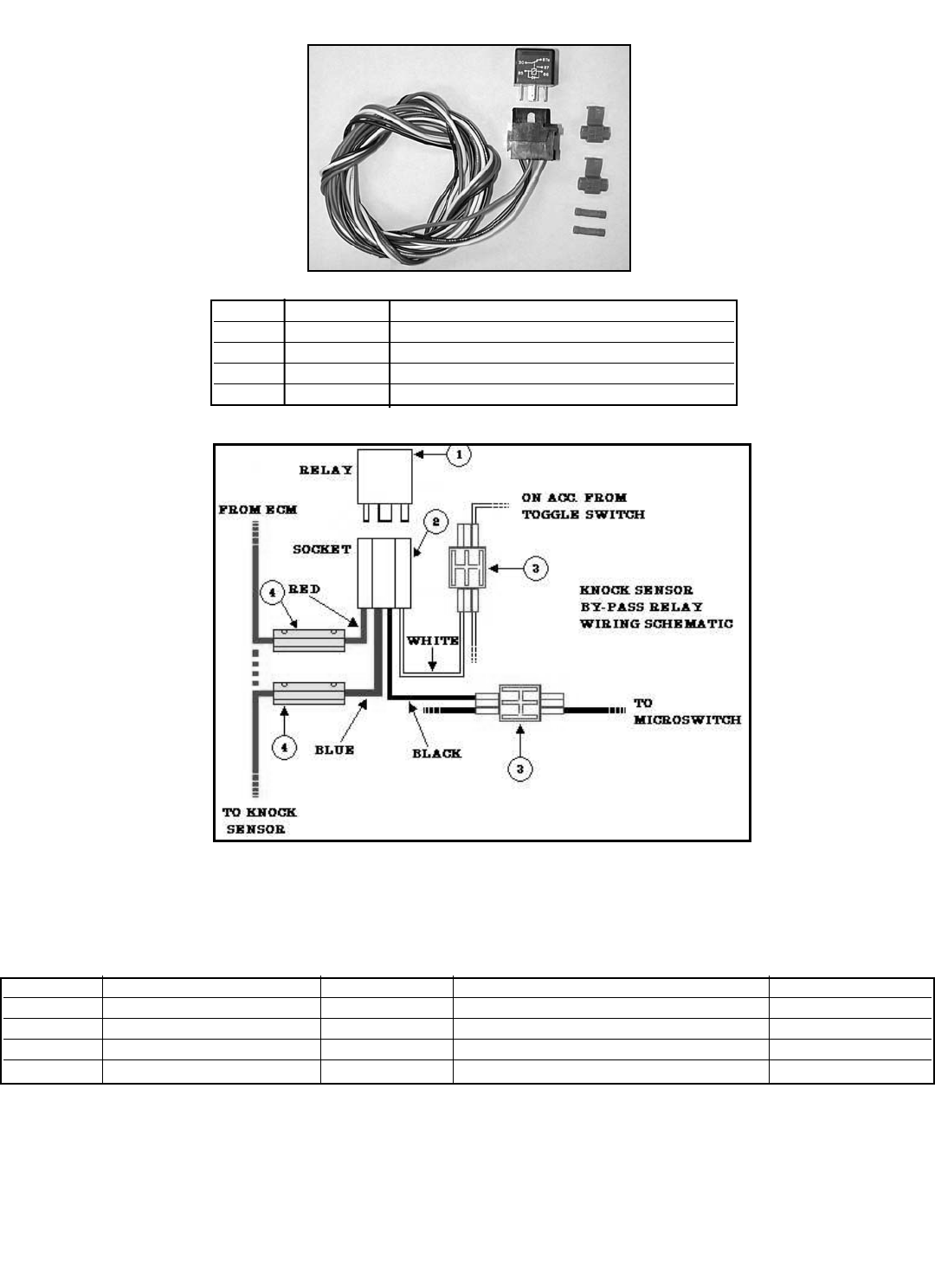
3.11 Knock Sensor By-Pass Relay Components Bill of Materials (BOM)
Item # Quantity Description
1 1 ea. 30 amp relay
2 1 ea. Knock Sensor Relay Harness
3 2 ea. 16/18 Splice Connector
4 2 ea. 16/18G Butt Connector
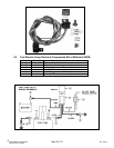
3.12 Knock Sensor By-Pass Relay Installation
Determine the location of the Knock Sensor By-Pass Relay. This should be as close to the ECM as
possible. Since the connectors are water-resistant, not waterproof, mount the relay in a location with
minimal chance of exposure to water.
Wire Color System Origin Destination Terminal Used
Red Knock Sensor By-Pass Output of ECM Relay Harness Butt Conn.
Blue Knock Sensor By-Pass Relay Harness Knock Sensor Butt Conn.
Black Sensor Ground Relay Harness Non-Grounded Side of Microswitch Splice Conn.
White Relay Power Relay Harness Arming Switch Splice Conn.