


© 2000 Directed Electronics, Inc. Vista, CA 17
plug-in harnesses
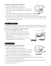
The LED operates at 2V DC. Make sure the LED wires are not shorted to ground because the LED will be damaged.
The LED fits into a
9
/32-inch mounting hole. Be sure to check for clearance prior to drilling the mounting hole.
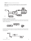
The Valet/program switch should be accessible from the driver’s seat. It plugs into the 2-pin blue port of the
control module. Since the system features Valet by remote, the Valet switch can be well hidden. Consider how
the switch will be used before choosing a mounting location. Check for rear clearance before drilling a
9
/32-inch
hole and mounting the switch. The GRAY wire in the two-pin plug may also be used as a (+) Ghost Switch input
and can be connected to any positive (+) switch in the vehicle (see Feature 9 in the Feature Descriptions section
of this guide).
NOTE: Please note for the customer the location of the Valet/program switch in the section pro-
vided in the Owner’s Guide.
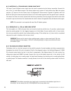
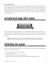
optional sensor harness, 4-pin connector
The four-pin shock sensor harness is optional and is not included with this unit. It can be used to add a Glass
Breakage Sensor (P/N 506T) or other optional sensors.
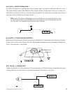
RED WIRE
The red wire supplies constant power to the optional sensor.
BLACK WIRE
The black wire supplies ground to the optional sensor.
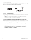
BLUE AND GREEN WIRES
The blue and green wires are multiplex inputs. They are both tied to the same zone. If an input of less than 0.8
seconds is supplied to either wire, the Warn-Away response will occur. An input longer than 0.8 seconds to either
wire will initiate the triggered sequence and report Zone 4.
valet/program switch, 2-pin blue plug
super-bright LED, 2-pin white plug