


16 © 2000 Directed Electronics, Inc. Vista, CA
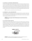
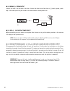
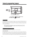
H1/10 BROWN (+) SIREN OUTPUT
Connect this wire to the red wire of the siren. Connect the black wire of the siren to (-) chassis ground, prefer-
ably at the same point that you connect the control module’s black ground wire.
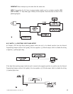
H1/11 RED (+) 12V CONSTANT POWER INPUT
Before connecting this wire, remove the supplied fuse. Connect to the positive battery terminal or the constant
12V supply to the ignition switch.
NOTE: Always use a fuse within 12 inches of the point you obtain (+)12V. Do not use the 15A fuse
in the harness for this purpose. This fuse protects the module itself.
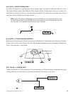
H1/12 RED/WHITE PROGRAMMABLE (-) 200 mA AUXILIARY CHANNEL/DELAYED ACCESSORY OUTPUT
If programmed for the default setting, this wire will provide a (-) pulse when the lock button on the factory
transmitter is pressed twice within three seconds. This output can be used to control optional accessories. If pro-
grammed for delayed accessory output, this wire will provide (-) ground when the ignition is turned off and will
continue to output (-) ground until a door is opened and then closed. This can be used to energize the acces-
sory circuit in the vehicle to keep the radio and other accessories on after the ignition is turned off.
IMPORTANT! Never use this wire to drive anything except a relay or a low-current input! This
transistorized output can only supply (-) 200 mA, and connecting directly to a solenoid, motor, or
other high-current device will cause the module to fail.