


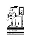
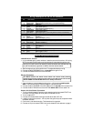

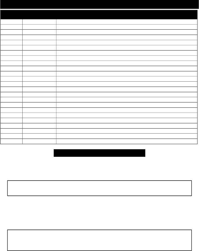
Wir ing De scrip tion for the 24- Pin Con nec tor
Pin Wire Color Con nects to
1
White/Blue Remotely Adjustable Dual-Zone Piezo Sensor input
2
White/Violet Pulse out before remote start (-) and upon disarming
3
Black/Gray RPM input
4
Blue/Green Reverse light input (+)
5
White Valet switch input (-)
6
Orange Glass Tampering Sensor input (-)
7
White/Black Hood trigger input (-)
8
Gray/Yellow Trunk trigger input (-)
9
Blue/White Brake light input (+) (and relay shown if manual transmission)
10
Black Ground for sensors, LED and PlainView 2 Switch
11
Red Power for Dual-Zone Piezo and Glass Tampering sensors
12
Black Ground (-)
13
Gray/Green Door lock output (+) or (-)
14
Green Armed output (-)
15
Violet/White Pulse out after remote start (-) and upon arming
16
Gray/Violet Auxiliary A output (-)
17
Gray/Orange Door unlock (+) or (-)
18
Red Battery (+) with 5-amp fuse
19
Violet LED output (+)
20
Yellow Siren (-)
21
Blue/Black Heater 2 relay output if needed (-)
22
Brown/Red Interior light supply input (+) or (-)
23
Gray Door trigger (+) or (-)
24
Blue/Orange Negative out when started
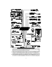
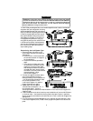
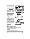
Starter and Ig ni tion Con nec tions
Im mo bi li za tion Cir cuits
1.In the underdash ignition switch wireloom, locate the one wire that carries +12V during
BOTH the cranking AND engine running cycles, and 0 volts when the ignition is off.
You may find two wires in the steering column wireloom that test this way. If
so, see the Secondary Ignition or Heater/AC wire section below.
2. Start the engine, then cut the ignition wire. The engine should stop running.
3. Connect the WHITE/BROWN wire to the key side of the ignition line.
4. Connect the GREEN/BLUE wire to the other side.
Starter Con nec tion
You MUST con nect the starter wires be fore the neu tral safety switch,
oth er wise the engine could be started while in gear. Be cer tain that both the
WHITE/GREEN and WHITE/BLUE wires are sol idly con nected.
1.Use a voltmeter to locate the one wire that carries +12V during the cranking cycle
ONLY. Cut this wire, then try to start the engine. It should not crank.
2. Con nect the WHITE/GREEN of the ACE 7500 wire to the key side of the cut starter line.
3. Connect the WHITE/BLUE wire of the ACE 7500 starter side of the cut starter line.
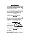
Heater/Air Con di tioner Con nec tion
1. Turn the vehicle’s heater/AC switch on and rotate the ignition key toward START one
increment at a time. Observe at which position the blower turns on.
2. Turn the engine OFF.
3. Connect the voltmeter black lead to ground and set the dial to DC volt.
4. Locate the one wire that carries +12V only when the ignition key is at the position where
the blower activates.
5. Cut the wire , then start the engine. The blower should not operate.
6. Connect the 12-pin connector’s GRAY wire to the heater/AC wire as shown on page 4.
6