


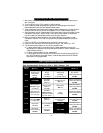

NOTE: If none of the troubleshooting techniques described corrects the
problem, perform the following diagnostics:
n Make sure the fuses are in the fuse hold ers and check the power and ground con nec tions.
nVer ify that the con trol unit con nec tors are prop erly in serted into the con trol unit.
nVerify the ig ni tion in put and out put wires are con nected to the true ig ni tion line instead
of a +12V line. See the Starter and Ig ni tion Connections section.
n Ver ify that the trans mit ters are pro grammed cor rectly.
NOTE: If the 20- amp fuse blows upon arm ing:
nDisconnect the ACE 7500’s two parking light wires, replace the 20-amp fuse and rearm.
If the fuse does not blow, one (or both) of the ve hi cle’s parking light wires is short ing.
n If the fuse blows while the parking light wires are dis con nected, the door locks are not
wired cor rectly. Re con nect the ve hi cle’s power lock ing sys tem to its origi nal con di tion,
then re test the volt ages as in di cated in the Door Locks sec tion.
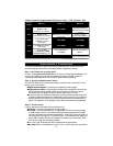
Step 4: Test the park ing lights.
Arm the sys tem with the re mote con trol.
nTwo flashes. This is the correct response, proceed to step 5.
nOne flash. If the parking lights flash only once, the ACE 7500 had pre vi ously
AutoArmed it self pas sively and by press ing but ton 1 the sys tem dis armed (re mote
dis arm ing is ac knowl edged with one parking light flash). Re peat step 1.
n No flashes. If no flashes, ver ify the parking light bulbs are op era tional. If not, they must
be re placed. If so, see the Parking Lights sec tion.
n Only one side flashes. If only the right or the left side parking lights flash, see the
Parking Lights sec tion.
Step 5: Test the door locks.
Arm the sys tem by press ing but ton 1 on the re mote con trol.
nDoors lock. This is the correct response, proceed to step 6.
nDoors do not lock. You ei ther se lected the wrong lock dia gram, programmed the wrong
lock polarity or con nected the wires in cor rectly. Re con nect the ve hi cle’s lock ing sys tem
to its origi nal con di tion, then re test as in di cated in the Door Locks sec tion.
WARN ING: If the doors do not lock, DO NOT ac ti vate the ve hi cle’s lock
switches. Do ing so may dam age the ACE 7500 con trol unit, the ve hi cle’s
elec tri cal sys tem and/or the power lock servo mo tors.
n Doors unlock. You ei ther se lected the wrong door lock dia gram or con nected the wires
in cor rectly. Re con nect the ve hi cle’s power lock ing sys tem to its origi nal con di tion, the n
re test the volt ages as in di cated in the Door Locks sec tion and wire the locks as in di cated.
n Only one door locks. You ei ther se lected the wrong door lock dia gram or con nected
the wires in cor rectly. Re con nect the ve hi cle’s power lock ing sys tem to its origi nal
con di tion, then re test the volt ages as in di cated in the Door Locks sec tion.
Step 6: Test the PlainView 2 Switch .
Test switch operation by entering programming mode as noted on page 16. If no response:
nVerify the WHITE/BROWN wire has +12V when the ignition is ON and 0V when
OFF. If not refer to Starter and Ig ni tion Connections section on page 6.
n Verify the WHITE wire rests at +5V, shows +3V when pressing the switch’s ✱ button
and 0V when pressing the blank button. If not, test the switch’s BLACK wire. It should
read 0V at rest, 0V when pressing ✱ , and 0V when pressing the blank button. If the
BLACK wire tests incorrectly, check the ground circuit. If both wires test correctly, the
valet code has been changed. Use CliffNet Wizard PRO to reset the PIN code.
19