


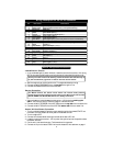

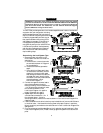
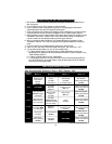

RPM Moni tor ing
The ACE 7500 monitors RPM which is REQUIRED for the operation of the remote engine
starting electronics as well as the anti-carjacking electronics and RPM-dependent AutoLock
feature. After powering up the system, you must perform the MANDATORY RPM
PROGRAMMING noted on page 13. Some newer vehicles do not have a conventional coil
marked (+) and (–). In these instances, you will need to locate the tach wire:
1. Try to locate the distributor cap which all spark plug wires run in to. There should be the
same number of plug wires as the number of cylinders. If there is an extra plug wire, the
vehicle has a separate coil.
2. Follow the extra plug wire to the coil module, which will have two or more wires.
a. If there are only two wires: one is the ignition, the other wire is the negative coil wire.
b.If there are more than two wires, only an oscilloscope will be 100% accurate in locating
the tach wire, but a digital voltmeter will often suffice. Set the meter to read AC
voltage, connect the negative lead of the meter to ground and probe the wire with the
positive lead. The wire that has the highest AC voltage while the engine is running is
usually the tach wire.
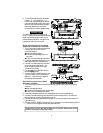
3. If the vehicle does not have a separate coil, look for the tach wire in a plug coming out of
the distributor. If no distributor can be found, there may be multiple coils. Each coil usually
has an ignition and a negative coil wire. The system will learn a single or multiple coil system.
4. If no coil or distributor can be found or reached, use the #60-226 RPM Alternator Sensor.
5. You can often connect to the negative side of any fuel injector. Most injectors are screwed
directly into the engine and have two wires. One is ignition and usually has a color common
to all, the other is the negative side and can be tested as described in step 2b above.
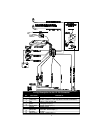
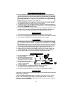
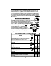
In stal la tion Op tions
1.In stal la tion Op tion 1 — Negative Coil
Con nect the BLACK/GRAY wire to the nega tive ter mi nal of the ig ni tion coil, nor mally
marked (–).
2. In stal la tion Op tion 2 — Fuel Injector Wire
a.On many engines with electronic fuel injection, there are two wires going to each
injector: a fuel-injector wire and a common ignition wire. The common ignition wire is
usually the same color at each injector (and may also be the same color as the ignition
line in the steering column). The injector wire is the other wire.
b.Connect the BLACK/GRAY wire to one of the injector wires.
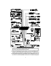
3.In stal la tion Op tion 3 — Tachometer Terminal (Not all cars have a tachometer terminal
— mostly older GM models have a tachometer terminal)
a. Locate the tachometer terminal on the distributor cap (this may be marked “tach”).
b.Connect the BLACK/GRAY wire to the tachometer terminal.
4. In stal la tion Op tion 4 — Optional Alternator Sensor (#60-226)
Follow the instructions provided in the Alternator Sensor kit.
5. In stal la tion Op tion 5 — Optional RPM Monitoring Module (#60-521)
a.Locate the coil wire that connects to the distributor.
b.Attach the RPM Monitoring Module to the coil wire.
c. Connect the RED, BLACK and WHITE wires on the RPM Monitoring Module to the
RED, BLACK and BLACK/GRAY wires of the system.
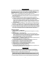
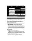
Trunk Trig ger
Vehicles with a ground-switching trunk light will interface directly with the ACE 7500 (on
positive switching Rolls-Royce vehicles, use a relay to invert polarity). The switch may be
located in or near the trunk latch or at the trunk light. If a switch cannot be located, you
must add a pin switch in a location away from water channels.
NOTE: If the ve hi cle has a dash board trunk ajar in di ca tor, in stall a 1- amp
di ode be tween the light and switch with the di ode band to ward the switch.
1. Connect the GRAY/YELLOW wire to the trunk switch (between the diode and switch).
11