


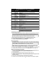

Fac tory Theft De ter rent By pass
The wiring noted be low is to dis arm a ve hi cle’s fac tory sys tem to per mit re mote start ing.
For more information on factory theft deterrent bypass, check your Clifford
Tech Support Database, visit www.clifforddealer.com (USER NAME =
roadshop PASSWORD = cliffg4) or call our toll-free Circuit City Technical
Support Hotline or AutoFax at 1-877-CLIFF-G4.
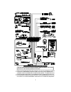
1. The BLUE/ORANGE wire is a negative out whenever the vehicle is remotely started. It
can be used for extra ignition relays or for factory alarm bypass.
2. The WHITE/VIOLET wire is a negative pulse out just prior to remote engine starting. It
can be used to pulse a factory disarm wire or unlock the doors. This wire also pulses when
the ACE 7500 is disarmed using the remote.
3. The VIO LET/WHITE wire is a nega tive pulse out af ter re mote en gine start ing. This can
be used to lock the doors after remote starting if the doors had been unlocked prior to
starting. This wire also pulses when the ACE 7500 is armed using the remote.
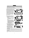
Re verse Lights
1. Ver ify that the re verse lights il lu mi nate when the trans mis sion is put in re verse.
2. Find the one wire in the kick panel that reads +12V only when the transmission is in reverse.
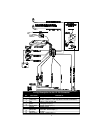
3. Con nect the BLUE/GREEN wire to the re verse light as shown on page 5.
Brake Lights
If working on a manual transmission vehicle, add a 3-amp diode terminal 30
of an optional relay as shown on pages 4-5 and connect it into the
BLUE/WHITE brake input wire. See also Manual Transmission section below.
1. Turn the ignition ON and press the brake pedal to make sure the brake light turns on.
2. Connect the black lead of the voltmeter to ground and set the dial to DC volt.
3. Probe one of the two wires at the brake pedal switch with the voltmeter red lead. The
voltmeter should read +12V when you press the brake pedal; 0 volts when released.
4. Connect the BLUE/WHITE wire to the brake light wire as shown on page 5.
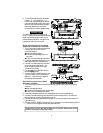
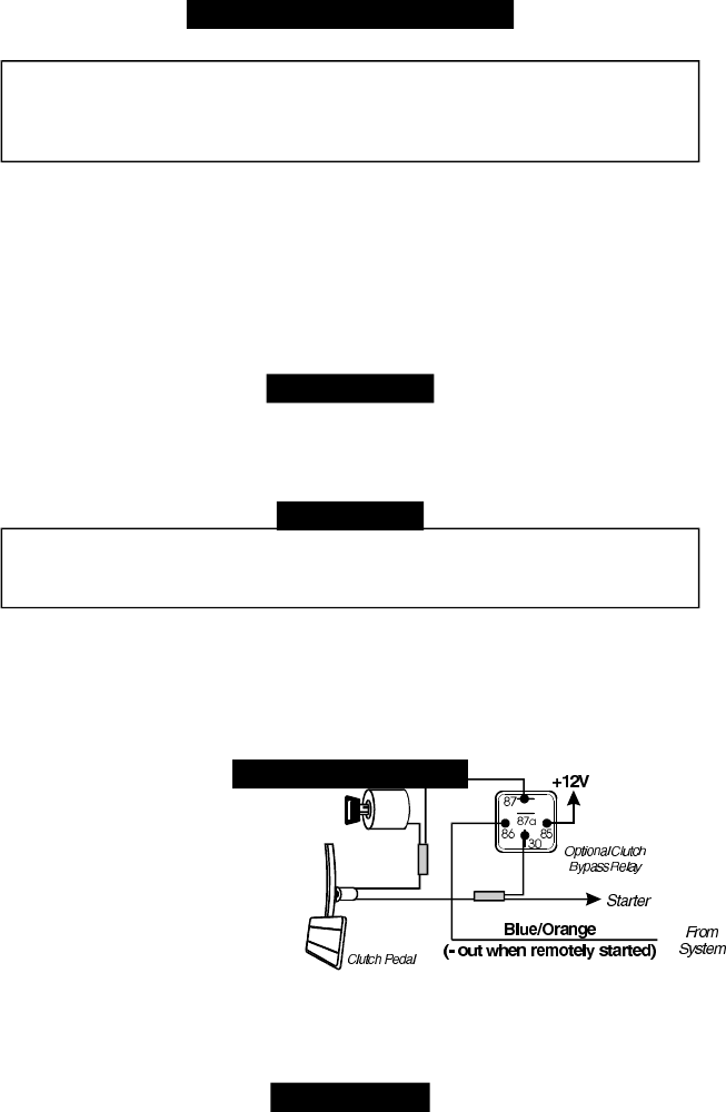
Man ual Trans mis sion
1. Find two wires going in to a connector
on the clutch pedal.
2. Unplug the clutch pedal connector,
then try to start the vehicle while
pressing the clutch pedal. The engine
should neither start nor crank.
3. Connect the BLUE/ORANGE wire to
an optional relay as shown.
4. Turn on the ignition.
5. Find the one wire near the emergency brake that carries +12V when
the emergency brake is engaged and 0V when it is disengaged.
6. Con nect the emergency brake wire to terminal 86 of a relay as shown on pages 4-5.
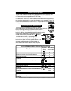
Die sel En gine
Use the built-in timer to crank the en gine 20 sec onds af ter the remote start command is received .
Using the 20 second delay:
Using the Installer-Programming instructions on page 17, set column 2, row 5 to “Diesel
Engine,” then immediately program RPMs, or use the CliffNet Wizard Pro installation
software to program the system. The CliffNet Wizard PRO will also allow you to customize
the delay to other than 20 seconds.
10