


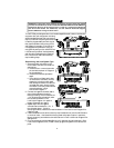

Im por tant In for ma tion
1.DO NOT dis con nect the bat tery ca bles! Make bat tery con nec tions by re mov ing the lug
nuts from the bat tery clamps with out de tach ing the clamp it self.
2. Turn off the in te rior lights or re move the dome light fuse bef ore start ing the in stal la tion ;
oth er wise, leav ing the door(s) open dur ing in stal la tion will drain the bat tery.
3. Use a volt me ter. DO NOT USE A TEST LIGHT! Test lights have a cur rent drain that
will dam age the ve hi cle’s on board com puter, and if you probe the wrong wire, could
de ploy the ve hi cle’s air bag(s).
4. Make all con nec tions with sol der and tape. DO NOT use bite- type con nec tors.
5. Route the sys tem’s ground and power wires di rectly to the ve hi cle bat tery.
6. Keep ex ten sion as short as pos si ble. Use same- gauge wire for short ex ten sions, larger gauge
for longer ex ten sions. DO NOT USE SPEAKER WIRE!
7. Dis cuss place ment of the LED, valet switch, win dow de cals, etc. with the ve hi cle owner
prior to in stal la tion.
8. DO NOT mount com po nents nor route wires near hot or mov ing ve hi cle parts. Clif ford
com po nents must not im pede ve hi cle serv ic ing or op era tion.
9. DO NOT mount any Clif ford sen sor in the en gine com part ment.
10.Fol low the sys tem’s Se quence of In stal la tion to en sure proper in stal la tion and test ing.
11.Place the own er’s man ual in the glove box.
Note: Clif ford Elec tron ics’ web site for Author ized Clif ford Deal ers has
de tailed de scrip tions of wire col ors and lo ca tions for most for eign and
do mes tic ve hi cles. In stal la tion dia grams and pro gram ming pro ce dures for
older Clif ford prod ucts are also avail able. See www.clif ford deal ers.com
(USER NAME=roadshop PASSWORD=cliffg4) for as sis tance 24- hours per day.
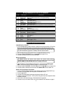
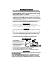
Re quired In stal la tion Tools
Voltmeter (set to “DC Volt”)
Wire crimper
Wire stripper
Electric drill and bits
Phillips screwdriver
Crescent wrench
Vinyl tubing
Rubber grommet
Convoluted tubing
Solder gun and solder
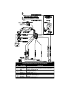
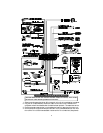
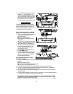
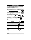
Sys tem Com po nents
The ACE 7500 kit contains the following components:
One Prewired 24-pin Connector Harness One Extended Range Receiver
One Prewired 12-pin Connector Harness One LED Status Indicator
One ACE 7500 Control Unit One Owner’s Manual
One PlainView 2 Coded Valet Switch One Hardware Kit
Two Remote Transmitters Two Window Decals
Remotely Adjustable Dual-Zone Piezo Sensor One High Output Insignia Siren
One Glass Tampering Sensor 18” CliffNet DataPort Extension Cable
3