


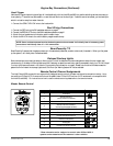
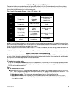

Passenger Compartment Connections
Control Unit and Extended Range Receiver
The IntelliGuard 6000 con trol unit must be in stalled in side the ve hi cle. Un der no cir cum sta nces should the unit
be in stalled un der the hood or other simi larly hos tile en vi ron ment.
1.Select an area behind the dash to mount the control unit using the supplied screws, but do not perm anently affix it until all wiring
and testing is complete.
2.Plug the extended range receiver in to the control unit. Mount the extended range receiver away fr om the control unit and run
the antenna either up the window pillar and affix it to the windscreen, or under the dash, away fro m metal. The position and
location of the receiver will effect remote control range. Do not fold the excess cable or antenna wire. Do not make hard, sharp
bends.
Door Trigger/Interior Light Supply
Please refer to the Door Trigger/Parking Lights section in this binder for information on polarity testing and connections.
Central Door Locking System
Please refer to the Door Locks section in this binder for information on circuit types and connections. When adding an IntelliSt art 4
to the Arrow 3, it is recommended that RPM-depending door locking be selected. The RPM-dependent d oor locking feature is only
available with the addition of the IntelliStart 4.
LED Status In di ca tor
Select a prominent location on the dash or console visible through all windows. Discuss placement w ith the owner.
1. Verify there is adequate space to accommodate the LED, then drill a 5/16” (8mm) hole and route the wires through it.
2. Mate the LED connectors to the VIOLET and BLACK wire connectors as shown in the diagram on page 2.
3. Press the LED into place.
PlainView 2 Coded Valet Switch
1. Discuss placement of the switch with the vehicle owner and avoid placing the switch where it can be pressed accidentally.
2.Verify there is adequate space behind the selected location to accommodate the switch.
3. Drill a 5/16” (8mm) mounting hole, then insert the wires through the hole and mount the switch.
4. Mate the switch’s locking connectors to the WHITE and BLACK locking connector.
5. Remove the adhesive backing and press into place.
Dual-Zone Piezo Sensor
Mount the Dual-Zone Piezo Sensor in the passenger compartment, not in the engine compartment.
1.Firmly mount the sensor near the base of the steering column (if the steering column has a rotating sleeve, firmly screw the sensor
to the interior firewall, kick panel or trunk wall). Make certain that the adjustment screw is acc essible.
2. Mate the sensor to the connector on the wireloom from the control unit with the BLACK, RED, ORANGE and BLUE wires.
Glass Tampering Sensor
Mount the Glass Tampering Sensor in the passenger compartment, not the engine compartment.
1.Mount the microphone holder so that it points into the passenger compartment, but will not be expos ed to direct sunlight.
2.Plug the microphone into the sensor (an optional second microphone can be added to vans and other l arge vehicles for increased
sensitivity and better discrimination).
3. Mate the sensor to the connector on the wireloom from the control unit with the BLACK, RED and ORAN GE wires.
In tel liGuard 6000/1298 3