


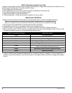
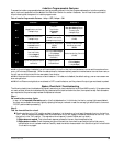

Wiring Description for the 4-Pin Connector
Pin Wire Color Con nects to
1 Green/Blue Ignition Output
2 White/Blue Starter Output
3 White/Brown Ignition Input
4 White/Green Starter Input
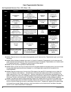
Wiring Description for the 22-Pin Connector
Pin Wire Color Con nects to
1 Gray/Blue Channel 4 output
2 Black Prewired to the Valet Switch and Glass Tampering Sensor
3 Blue Piezo Sensor input - Warning Zone
4 White Valet Switch input (-)
5 Green Armed output (-)
6 Red Power for the Piezo and Glass Tamp. Sensors
7 Orange Glass Tampering Sensor input
8 Gray/Yellow Trunk and hood trigger input (-)
9 Orange Piezo Sensor input - Trigger Zone
10 Black Battery negative
11 Brown Parking light output (+)
12 Black Ground for both sensors, LED connectors, and Valet Switch
13 Gray/Green Door lock output (+) or (-)
14 Gray/Orange Door unlock output (+) or (-)
15 Gray/Violet Channel 2 output
(-)
16 Red Battery positive through 5 Amp fuse
17 Red/White Battery positive with 20 Amp fuse
18 Violet Prewired to the LED connector
19 Brown/Red Interior light supply (+) or (-)
20 Gray Door trigger input (+) or (-)
21 Yellow Siren output (-) (black wire on Siren)
22 Brown Parking light output (+)
2 In tel liGuard 6000/1298