


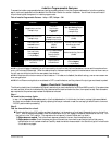

System Checklist & Troubleshooting (Continued)
Step 4.
Test the park ing lights.
Arm the sys tem.
n
Two flashes. This is the correct response, proceed to step 5.
n
One flash. If the parking lights flash only once, the IntelliGuard 6000 had pre vi ously AutoArmed it self pas sively and by
press ing the arm/disarm but ton the sys tem dis armed (re mote dis arm ing is ac knowl edged with one chirp and one parking light
flash). Disarm and rearm the system.
n
No flashes. If no flashes, ver ify the parking light bulbs are op era tional. If not, they must be re placed. I f so, re peat steps 1-5 of
the Parking lights sec tion in this binder.
n
Only one side flashes. If only the right or the left side parking lights flash, see the Parking lights sec tion in this binder.
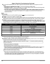
Step 5.
Test the door locks.
Arm the sys tem.
n
Doors lock. This is the correct response, proceed to step 6.
n
Doors do not lock. You ei ther se lected the wrong door lock dia gram , con nected the wires in cor rectly, or a serv o may be
required. Re con nect the ve hi cle’s power lock ing sys tem to its origi nal con di tion, then re test the volt ages as in di cated in the
Door Lock ing/Un lock ing sec tion of this binder and wire the locks as in di cated. Polarity programming should also be ver ified.
WARN ING: If the doors do not lock, DO NOT ac ti vate the ve hi cle’s lock switches. If the locks h ave been
mis wired, do ing so may dam age the IntelliGuard 6000 con trol unit, the ve hi cle’s elec tri cal sys tem and/or the
power lock servo mo tors.
n
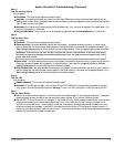
Doors unlock. You ei ther se lected the wrong door lock dia gram, con nected the wires in cor rectly, or a servo may be required.
Re con nect the ve hi cle’s power lock ing sys tem to its origi nal con di tion, then re test the v olt ages as in di cated in the Door
Lock ing/Un lock ing sec tion of this binder and wire the locks as in di cated.
n
Only one door locks. You ei ther se lected the wrong door lock dia gram, con nected the wires in cor rectly, or a servo may be
required. Re con nect the ve hi cle’s power lock ing sys tem to its origi nal con di tion, then re test the volt ages as in di cated in the
Door Lock ing/Un lock ing sec tion of this binder and wire the locks as in di cated.
Step 6.
Test the LED.
Arm the system.
n
Flashes repeatedly. This is the correct response, proceed to step 7.
n
No flashes. If the LED does not flash, ver ify that the LED’s VIO LET and BLACK wires are sol idly con nected t o the same
color wires on the IntelliGuard 6000’s wire loom. Warn ing: This is a 2- volt LED, test ing with 12 volts will de stroy the LED.
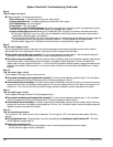
Step 7.
Test the Valet Switch.
n
Test the valet code and switch operation. Use the instructions provided on page 7 to enter program ming mode. If the system
enters programming mode, the switch and valet code are in operating order. If not, perform the fol lowing tests:
n
Test the WHITE wire at the control unit connector. It should rest at 5 volts. When pressing the m
arked side, it should read 3
volts and when pressing the unmarked side it should read 0 volts. If any reading is incorrect, mov e the voltmeter to the
BLACK wire at the valet switch. It should read 0 volts at rest, 0 volts when the marked side marke d is pressed, and 0 volts
when the unmarked side is pressed. If the BLACK wire tests correctly and the WHITE wire does not, replace the switch. If
the BLACK wire tests incorrectly, repair the ground circuit. If both wires test correctly, then th
e valet code has been changed.
Use the CliffNet Wizard Pro to reset the valet code.
In tel liGuard 6000/1298 11