


Passenger Compartment Connections (Continued)
Trunk Trigger
Vehicles with a ground-switching trunk light will interface directly with the IntelliGuard 6000 (on positive switching Rolls-Royce vehicles,
use a relay to invert polarity). The switch may be located in or near the trunk latch or at the tru nk light. If a switch cannot be
located, you must add a pin switch in a location away from water channels.
NOTE: If the ve hi cle has a dash board trunk ajar in di ca tor, in stall a 1A di ode be tween the light and switch with
the di ode band point ing to ward the switch.
Parking Light
1.Connect the GRAY/YELLOW wire to the trunk switch. See the Door Trigger/Parking light section in this binder.
Channel 2 with Selectable Output Type
The channel 2 output (GRAY/VIOLET wire) can be programmed as either pulsed, latched or timed and ca n be programmed to
operate only when the system is disarmed (e.g., for use as a remote trunk release). Channel 2 outp ut is activated by pressing the
button on the remote control. The factory setting is pulsed output (0.5 second ground). The latche d output stays at ground until the
button is pressed a second time, and the timed output stays at ground for any selected duration be tween one second and four
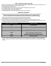
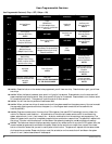
minutes. See Installer-Programmable Features on page 9 for information on programming the output type and/or disabling operation
while the system is disarmed. If the system is set to arm and disarm using two different buttons o n the remote, this wire can be
programmed as a negative output when unlock (disarm) is transmitted a second time. See the program ming instructions on page 9.
See the Timer section of this binder for information on using the system timer for Window RollUp, t imed
headlight activation, or as a turbo-timer for cool down.
Channel 4 with Selectable Output Type and AutoActivation
The channel 4 output (GRAY/BLUE wire) can be programmed as either pulsed, latched or timed. It can also be programmed to
automatically activate every time the system is remotely armed. The output is activated by pressing the from the remote. Current is
limited to 0.25 amp. AutoActivation is perfect when programmed as a timed-output to close the power windows and sunroof on vehicles
that have an all-close feature (see the Timer section of this binder for more information on wiring this feature) . See Installer-Programmable
Features on page 9 for more information on programming output type and/or enabling the AutoActivation featur e.
Starter and Ignition Immobilization Circuits
1. Locate the ignition switch wireloom under the dash and use a voltmeter to locate the one wire that carries +12V throughout
BOTH the cranking AND engine running cycles, and 0 volts when the ignition is off.
2. Start the engine, then cut the ignition wire. The engine should stop running.
3. As shown on page 2, connect the WHITE/BROWN wire to the key side of the cut ignition line.
4.Connect the GREEN/BLUE wire to the engine side of the cut ignition line.
5.Use a voltmeter to locate the one wire that carries +12V during the cranking cycle ONLY. Cut this wire, then try to start the
engine. It should not crank.
6. Con nect the WHITE/GREEN wire to the key side of the cut starter line.
7.Connect the WHITE/BLUE wire to the engine side of the cut starter line.
NOTE: The starter cir cuit may carry a very high cur rent. Be cer tain that the starter wire con ne c tions are solid.
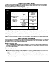
Engine Bay Connections
High Output Insignia Siren
Mount the siren in the engine compartment away from hot or moving parts and where it cannot be reac hed from under the vehicle,
preferably opposite the exhaust system. Point the siren down to avoid water collection (see the il lustration).
1.You must firmly secure the siren to the engine bay firewall or an inner wing using all three sheet metal screws supplied.
2. Us ing the sup plied con nec tor, connect the wireloom’s YELLOW wire to the BLACK siren wire.
3. Connect the RED wire through the 5A fuse coming from the battery positive cable clamp.
4 In tel liGuard 6000/1298