


7
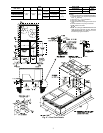
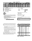
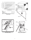
BOTTOM POWER CHART, THESE HOLES
REQUIRED FOR USE WITH ACCESSORY
PACKAGES — CRBTMPWR002A00
(
POWER
AND CONTROL) AND CRBTMPWR004A00
(POWER, CONTROL, AND GAS)
THREADED
CONDUIT
SIZE
WIRE
USE
REQURED
HOLE SIZES
(MAX.)
1
/
2
″
″ ″
″
[12.7]
24 V
7
/
8
″
″″
″
[22.2]
1
1
/
4
″
″ ″
″
[31.7]
Power 1
3
/
4
″
″″
″
[44.4]
3/
4
″
″ ″
″
[19] FPT
Gas 1
5
/
8
″
″″
″
[41.3]
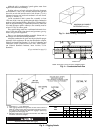
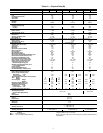
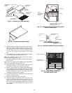
UNIT
48TF
STANDARD
UNIT WEIGHT
DURABLADE
ECONOMIZER
WEIGHT
ECONOMI$ER
WEIGHT
CORNER
WEIGHT (A)
CORNER
WEIGHT (B)
CORNER
WEIGHT (C)
CORNER
WEIGHT (D)
“H” “J” “K” “L”
Lb Kg Lb Kg Lb Kg Lb Kg Lb Kg Lb Kg Lb Kg ft-in. [mm] ft-in. [mm] ft-in. [mm] ft-in. [mm]
D/E/F008
870 395 44 20 62 28 189 86 161 73 239 109 280 127 1-2
7
/
8
[378] 3-5
5
/
16
[1050] 2-9
11
/
16
[856] 2- 2
7
/
16
[672]
D/E/F012
1035 469 44 20 62 28 225 102 192 87 285 129 333 151 2-5
7
/
8
[759] 4-1
5
/
16
[1253] 3-0
3
/
8
[924] 2-10
7
/
16
[875]
D/E014
1050 476 44 20 62 28 228 103 195 88 289 131 338 153 1-2
7
/
8
[378] 4-1
5
/
16
[1253] 3-0
3
/
8
[924] 2-10
7
/
16
[875]
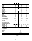
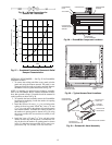
CONNECTION SIZES
A
1
3
/
8
″
″″
″
Dia [35] Field Power Supply Hole
B
2
1
/
2
″
″″
″
Dia [64] Power Supply Knockout
C
1
3
/
4
″
″″
″
Dia [44] Charging Port Hole
D
7
/
8
″
″″
″
Dia [22] Field Control Wiring Hole
E
3
/
4
″
″ ″
″
[19] - 14 NPT Condensate Drain
F
1
/
2
″
″″
″
[13] - 14 NPT Gas Connection 48TFD008
3
/
4
″
″ ″
″
[19] - 14 NPT Gas Connection 48TFE,F008
48TFD,E012 & 014, 48TJF012
G
2
″
″″
″
Dia [51] Power Supply Knockout
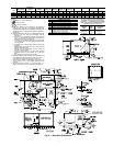
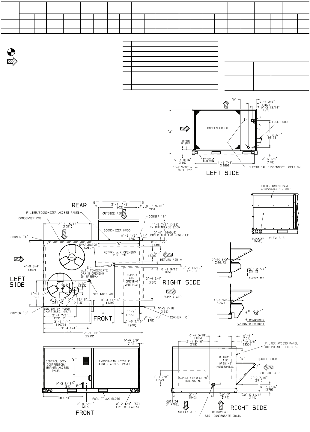
NOTES:
1. Dimensions in [ ] are in millimeters.
2. Center of gravity.
3. Direction of airflow.
4. On vertical discharge units, ductwork to be attached to
accessory roof curb only. For horizontal discharge units,
field-supplied flanges should be attached to horizontal dis-
charge openings, and all ductwork should be attached to
the flanges.
5. Minimum clearance (local codes or jurisdiction may prevail):
a. Between unit, flue side and combustible surfaces,
36 in. [914].
b. Bottom of unit to combustible surfaces (when not using
curb), 1 in. [25]. Bottom of base rail to combustible sur-
faces (when not using curb) 0 inches.
c. Condenser coil, for proper airflow, 36 in. [914] one side,
12 in. [304] the other. The side getting the greater clear-
ance is optional.
d. Overhead, 60 in. [1624] to assure proper condenser fan
operation.
e. Between units, control box side, 42 in. [1067] per NEC
(National Electrical Code).
f. Between unit and ungrounded surfaces, control box
side, 36 in. [914] per NEC.
g. Between unit and block or concrete walls and other
grounded surfaces, control box side, 42 in. [1067] per
NEC.
h. Horizontal supply and return end, 0 inches.
6. With the exception of the clearance for the condenser coil
and combustion side as stated in notes 5a, b and c, a
removable fence or barricade requires no clearance.
7. Units may be installed on combustible floors made from
wood or Class A, B, or C roof covering material if set on
base rail.
8. The vertical center of gravity is 1
′
-7
″
[483] for 008, 1
′
-11
″
[584] for 012 and 014 up from the bottom of the base rail.
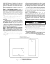
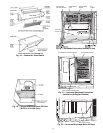
Fig. 6 — Base Unit Dimensions