


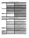

40
Main Burners —
At the beginning of each heating sea-
son, inspect for deterioration, blockage due to corrosion or oth-
er causes. Observe the main burner flames and replace burners
if necessary.
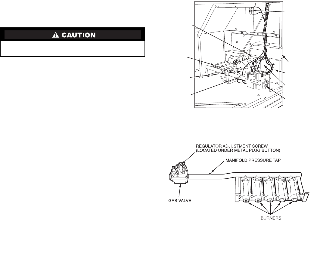
REMOVAL AND REPLACEMENT OF GAS TRAIN
(Fig. 52 and 53)
1. Shut off manual gas valve.
2. Shut off power to unit and tag disconnect.
3. Slide out burner section side panel (not shown).
4. Disconnect gas piping at unit gas valve.
5. Remove wires connected to gas valve. Mark each wire.
6. Remove wires from ignitor and sensor wires at the Inte-
grated Gas Unit Controller (IGC).
7. Remove the 2 screws that attach the burner rack to the
vestibule plate.
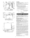
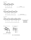
8. Slide the burner tray out of the unit (Fig. 53).
9. To reinstall, reverse the procedure outlined above.
CLEANING AND ADJUSTMENT
1. Remove burner rack from unit as described in Removal
and Replacement of Gas Train section on this page.
2. Inspect burners; if dirty, remove burners from rack.
3. Using a soft brush, clean burners and cross-over port as
required.
4. Adjust spark gap. See Fig. 54.
5. Reinstall burners on rack.
6. Reinstall burner rack as described in Removal and Re-
placement of Gas Train section.
Replacement Parts —
A complete list of replacement
parts may be obtained from any Carrier distributor upon
request.
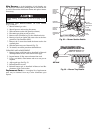
When working on gas train, do not hit or plug orifice
spuds.
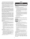
INDUCED-
DRAFT
MOTOR
MOUNTING
PLATE
INDUCED-
DRAFT
MOTOR
MANIFOLD
PRESSURE
TAP
VESTIBULE
PLATE
FLUE
EXHAUST
ROLLOUT
SWITCH
BLOWER
HOUSING
GAS
VALVE
BURNER
SECTION
Fig. 52 — Burner Section Details
Fig. 53 — Burner Tray Details