


35
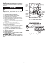
5. After a call for heating, the main burners should light
within 5 seconds. If the burners do not light, then there is
a 22-second delay before another 5-second ignition try.
If the burners still do not light, the time delay is repeated.
If the burners do not light within 15 minutes, there is a
lockout. To reset the control, break the 24 v power to W1.
6. The evaporator-fan motor will turn on 45 seconds after
the burners are ignited.
7. The evaporator-fan motor will turn off 45 seconds after
the thermostat temperature is satisfied.
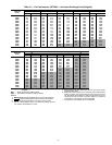
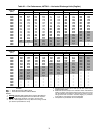
8. Adjust airflow to obtain a temperature rise within the
range specified on the unit nameplate and in Table 1A
or 1B.
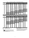
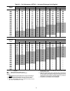
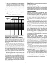
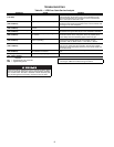
Table 24 — Altitude Compensation*
*As the height above sea level increases, there is less oxygen.
Therefore, heat input rate should be reduced at higher altitudes.
†Orifice available through your local distributor.
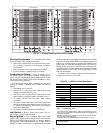
Integrated Gas Controller (IGC) Operation
NOTE: The default value for the evaporator-fan motor ON and
OFF delay is 45 seconds. The Integrated Gas Controller (IGC)
modifies this value when abnormal limit switch cycles occur.
Based upon unit operating conditions, the ON delay can be
reduced to 0 seconds and the OFF delay can be extended to
180 seconds.
When one flash of the LED (light-emitting diode) is ob-
served, the evaporator-fan ON/OFF delay has been modified.
If the limit switch trips at the start of the heating cycle during
the evaporator ON delay, the time period of the ON delay for
the next cycle will be 5 seconds less than the time at which the
switch tripped. (Example: If the limit switch trips at 30 sec-
onds, the evaporator-fan ON delay for the next cycle will occur
at 25 seconds.) To prevent short-cycling, a 5-second reduction
will only occur if a minimum of 10 minutes has elapsed since
the last call for heating.
The evaporator-fan OFF delay can also be modified. Once
the call for heating has ended, there is a 10-minute period dur-
ing which the modification can occur. If the limit switch trips
during this period, the evaporator-fan OFF delay will increase
by 15 seconds on the next cycle. A maximum of 9 trips can oc-
cur, extending the evaporator-fan OFF delay to 180 seconds.
To restore the original default value, reset the power to the unit.
TO SHUT OFF UNIT — Set system selector switch at OFF
position. Resetting heating selector lever below room tempera-
ture will shut unit off temporarily until space temperature falls
below thermostat setting.
Safety Relief —
A soft-solder joint at the suction line
Schrader port provides pressure relief under abnormal tempera-
ture and pressure conditions.
Ventilation (Continuous Fan) —
Set fan and system
selector switches at ON and OFF positions, respectively.
Evaporator fan operates continuously to provide constant air
circulation. When the evaporator-fan selector switch is turned
to the OFF position, there is a 30-second delay before the fan
turns off.
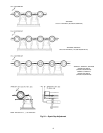
Operating Sequence
COOLING, UNITS WITHOUT ECONOMIZER — When
thermostat calls for cooling, terminals G and Y1 are energized.
The indoor (evaporator) fan contactor (IFC) and compressor
contactor no. 1 (C1) are energized, and evaporator-fan motors,
compressor no. 1, and both condenser fans start. The condenser-
fan motor runs continuously while unit is cooling. If the thermo-
stat calls for a second stage of cooling by energizing Y2, com-
pressor contactor no. 2 (C2) is energized and compressor no. 2
starts.
When the thermostat is satisfied, C1 and C2 are deener-
gized and the compressors and outdoor (condenser) fan motors
(OFM) shut off. After a 30-second delay, the indoor (evapora-
tor) fan motor (IFM) shuts off. If the thermostat fan selector
switch is in the ON position, the evaporator motor will run
continuously.
HEATING, UNITS WITHOUT ECONOMIZER — When
the thermostat calls for heating, terminal W1 is energized. In
order to prevent thermostat short-cycling, the unit is locked
into the Heating mode for at least 1 minute when W1 is ener-
gized. The induced-draft motor (IDM) is then energized and
the burner ignition sequence begins. The indoor (evaporator)
fan motor (IFM) is energized 45 seconds after a flame is ignit-
ed. On units equipped for two stages of heat, when additional
heat is needed, W2 is energized and the high-fire solenoid on
the main gas valve (MGV) is energized. When the thermostat
is satisfied and W1 and W2 are deenergized, the IFM stops af-
ter a 45-second time-off delay.
COOLING, UNITS WITH DURABLADE ECONO-
MIZER — When the outdoor-air temperature is above the
OAT (outdoor-air thermostat) setting and the room thermostat
calls for cooling, compressor contactor no. 1 is energized to
start compressor no. 1 and the outdoor (condenser) fan motor
(OFM). The indoor (evaporator) fan motor (IFM) is energized
and the economizer damper moves to the minimum position.
Upon a further call for cooling, compressor contactor no. 2 will
be energized, starting compressor no. 2. After the thermostat is
satisfied, the damper moves to the fully closed position when
using an auto fan or to the minimum position when using a
continuous fan.
When the outdoor-air temperature is below the OAT setting
and the thermostat calls for cooling, the economizer dampers
move to the minimum position. If the supply-air temperature is
above 14 C (57 F), the damper continues to open until it reach-
es the fully open position or until the supply-air temperature
drops below 11 C (52 F).
When the supply-air temperature falls to between 14 C
(57 F) and 11 C (52 F), the damper will remain at an intermedi-
ate open position. If the supply-air temperature falls below
11 C (52 F), the damper will modulate closed until it reaches
the minimum position or until the supply-air temperature is
above 11 C (52 F). When the thermostat is satisfied, the damp-
er will move to the fully closed position when using an auto fan
or to the minimum position when using a continuous fan.
ELEVATION
m or km
(ft)
31.4, 50.4, AND 59.8 kW
(107,000, 172,000 AND
204,000 BTUH
NOMINAL INPUT
65.6 kW
(224,000 BTUH)
NOMINAL INPUT
Natural
Gas
Orifice
Size†
Liquid
Propane
Orifice
Size†
Natural
Gas
Orifice
Size†
Liquid
Propane
Orifice
Size†
0-610 m (0-2,000)
3.0 (31) 2.4 (41) 3.2 (30) 2.5 (38)
610 m (2,000)
2.9 (32) 2.3 (42) 3.2 (30) 2.5 (39)
914 m (3,000)
2.9 (32) 2.3 (42) 3.0 (31) 2.4 (40)
1.22 km (4,000)
2.9 (32) 2.3 (42) 2.9 (32) 2.4 (41)
1.52 km (5,000)
2.8 (33) 2.2 (43) 2.8 (33) 2.3 (42)
1.83 km (6,000)
2.8 (34) 2.2 (43) 2.8 (34) 2.2 (43)
2.13 km (7,000)
2.8 (35) 2.1 (44) 2.8 (35) 2.2 (43)
2.44 km (8,000)
2.7 (36) 2.1 (44) 2.7 (36) 2.1 (44)
2.74 km (9,000)
2.6 (37) 2.0 (45) 2.6 (37) 2.1 (44)
3.05 km (10,000)
2.5 (38) 2.0 (46) 2.5 (38) 2.0 (45)
3.35 km (11,000)
2.5 (39) 1.9 (47) 2.5 (39) 2.0 (45)
3.66 km (12,000)
2.4 (40) 1.9 (47) 2.4 (40) 2.0 (46)
3.96 km (13,000)
2.4 (41) 1.9 (48) 2.4 (41) 1.9 (47)
4.27 km (14,000)
2.3 (42) 1.9 (48) 2.3 (42) 1.9 (47)