


2
SLAB MOUNT (Horizontal Units Only) — Provide a level
concrete slab that extends a minimum of 152 mm (6 in.)
beyond unit cabinet. Install a gravel apron in front of con-
denser coil air inlet to prevent grass and foliage from obstruct-
ing airflow.
NOTE: Horizontal units may be installed on a roof curb if
required.
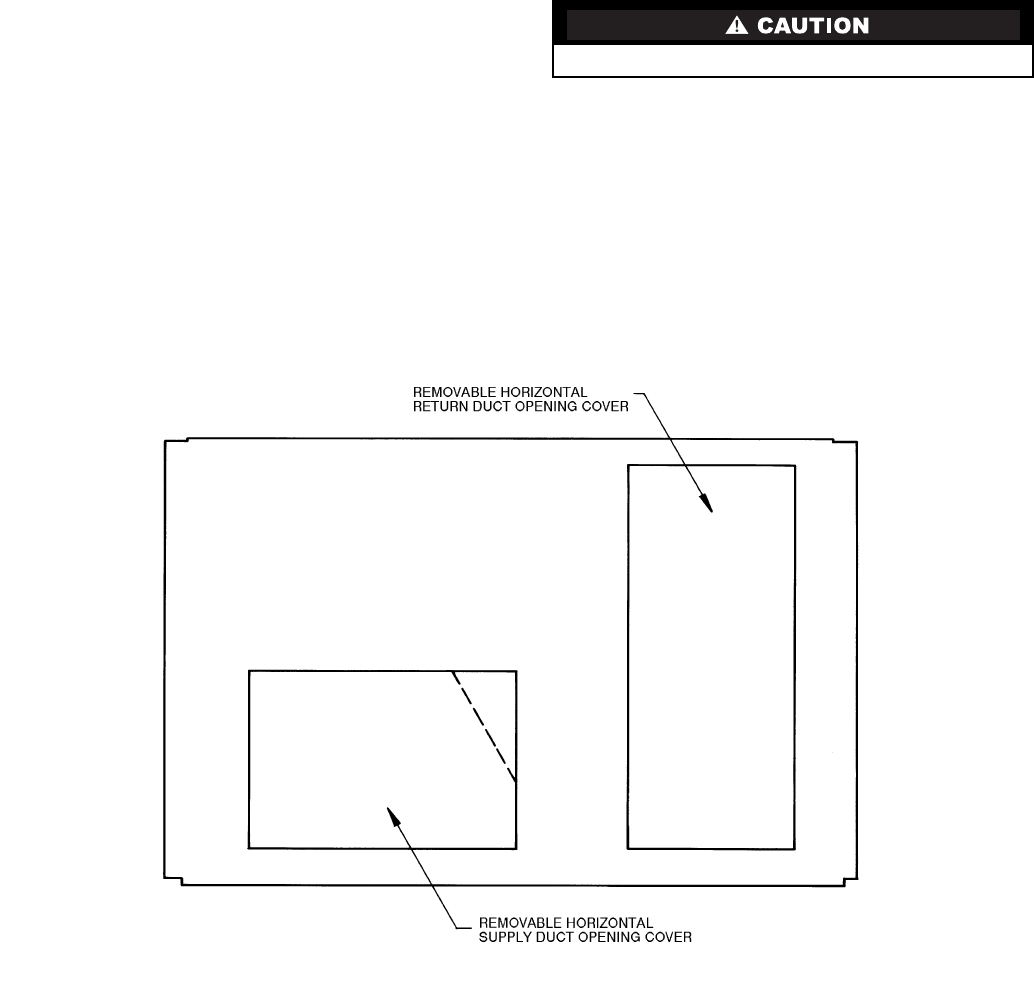
Step 2 — Field Fabricate Ductwork —
Secure all
ducts to roof curb and building structure on vertical units. Do
not connect ductwork to unit. For horizontal applications, field-
supplied flanges should be attached to horizontal discharge
openings and all ductwork secured to the flanges. Insulate and
weatherproof all external ductwork, joints, and roof openings
with counter flashing and mastic in accordance with applicable
codes.
Ducts passing through an unconditioned space must be in-
sulated and covered with a vapor barrier.
If a plenum return is used on a vertical unit, the return
should be ducted through the roof deck to comply with applica-
ble fire codes.
A minimum clearance is not required around ductwork.
Cabinet return-air static shall not exceed –87 Pa (–.35 in. wg)
with Durablade economizer, –26 Pa (–.30 in. wg) with
EconoMi$er or –112 Pa (–.45 in. wg) without economizer.
These units are designed for a minimum heating operation
continuous return-air temperature of 10 C (50 F) (dry bulb), or
an intermittent operation down to 7 C (45 F) (dry bulb), such as
when used with a night set-back thermostat.
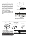
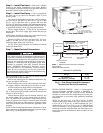
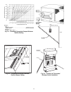
Step 3 — Install External Trap for Condensate
Drain —
The unit’s 19-mm (
3
/
4
-in.) condensate drain con-
nections are located at the bottom and side of the unit. Unit dis-
charge connections do not determine the use of drain connec-
tions; either drain connection can be used with vertical or hori-
zontal applications.
When using the standard side drain connection, make sure
the plug (Red) in the alternate bottom connection is tight before
installing the unit.
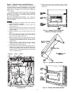
To use the bottom drain connection for a roof curb installa-
tion, relocate the factory-installed plug (Red) from the bottom
connection to the side connection. See Fig. 4. The piping for
the condensate drain and external trap can be completed after
the unit is in place.
All units must have an external trap for condensate drain-
age. Install a trap at least 102-mm (4-in.) deep and protect
against freeze-up. If drain line is installed downstream from the
external trap, pitch the line away from the unit at 25 mm (1 in.)
per 3 m (10 ft) of run. Do not use a pipe size smaller than the
19-mm (
3
/
4
-in.) unit connection.
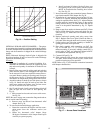
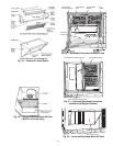
Step 4 — Rig and Place Unit —
Inspect unit for
transportation damage. File any claim with transportation
agency. Keep unit upright and do not drop. Spreader bars are
not required if top crating is left on unit. Rollers may be used to
move unit across a roof. Level by using unit frame as a refer-
ence. See Tables 1A and 1B and Fig. 5 for additional informa-
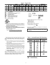
tion. Operating weight is shown in Tables 1A and 1B and
Fig. 5.
Lifting holes are provided in base rails as shown in Fig. 5
and 6. Refer to rigging instructions on unit.
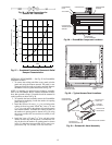
POSITIONING — Maintain clearance around and above unit
to provide minimum distance from combustible materials,
proper airflow, and service access. See Fig. 6.
Do not install unit in an indoor location. Do not locate unit
air inlets near exhaust vents or other sources of contaminated
air.
Be sure that unit is installed so that snow will not block the
combustion intake or flue outlet.
Unit may be installed directly on wood flooring or on Class
A, B, or C roof-covering material when roof curb is used.
(Copy continued on page 4.)
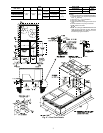
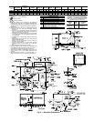
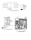
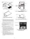
All panels must be in place when rigging.
Fig. 1 — Horizontal Conversion Panels