


8
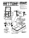
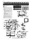
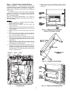
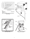
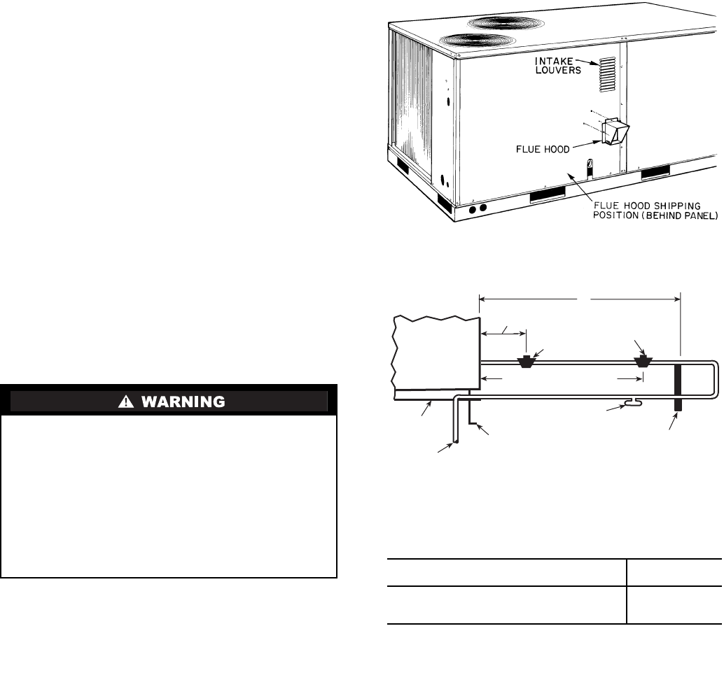
Step 5 — Install Flue Hood —
Flue hood is shipped
screwed to the burner compartment access panel. Remove
from shipping location and, using screws provided, install flue
hood and screen in location shown in Fig. 7.
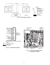
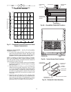
Step 6 — Install Gas Piping —
Unit is equipped for
use with type of gas shown on nameplate. Refer to local
building codes.
For natural gas applications, gas pressure at unit gas connec-
tion must not be less than 13.5 kPa (4.0 in. wg) (17.0 kPa
[5.0 in. wg] in high heat units) or greater than 44.0 kPa
(13.0 in. wg) while unit is operating. For liquid propane applica-
tions, the gas pressure must not be less than 17.0 kPa (5.0 in. wg)
or greater than 44.0 kPa (13.0 in. wg) at the unit connection.
Size gas supply piping for 1.7 kPa (0.5 in. wg) maximum
pressure drop. Do not use supply pipe smaller than unit gas
connection.
NOTE: When installing gas piping to gas valve inlet, use prop-
erly sized back-up wrench on inlet flange flats.
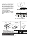
Support gas piping as shown in the table in Fig. 8. For ex-
ample, a 19 mm (
3
/
4
-in.) gas pipe must have one field-
fabricated support beam every 2.4 m (8 ft).
See Fig. 8 for typical pipe guide and locations of external
manual gas shutoff valve.
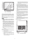
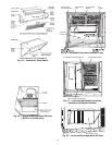
Step 7 — Make Electrical Connections
FIELD POWER SUPPLY — All units are factory wired for
the voltage shown on the nameplate.
Refer to unit label diagram for additional information. Pig-
tails are provided for field service.
When installing units, provide a disconnect per local codes.
Use copper conductors only when splice connectors are used.
All field wiring must comply with local requirements.
Install conduit through side panel openings indicated in
Fig. 6. Route power lines through connector to terminal con-
nections as shown in Fig. 9.
Voltages between phases must be balanced within 2% and
the current within 10%. Use the formula shown in Table 2,
Note 2 to determine the percentage of voltage imbalance. Op-
eration on improper line voltage or excessive phase imbalance
constitutes abuse and may cause damage to electrical compo-
nents. Such operation would invalidate any applicable Carrier
warranty.
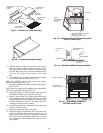
NOTE: If field-installed thru-the-bottom connections are used,
refer to the accessory installation instructions for power wiring.
Refer to Fig. 6 for drilling holes in basepan.
FIELD CONTROL WIRING — Install a Carrier-approved
accessory thermostat assembly according to installation in-
structions included with the accessory. Locate thermostat
assembly on a solid wall in the conditioned space to sense aver-
age temperature in accordance with thermostat installation
instructions.
NOTE: For wire runs up to 15 m (50 ft), use no. 18 AWG
(American Wire Gage) insulated wire (35 C minimum). For 15
to 23 m (51 to 75 ft), use no. 16 AWG insulated wire (35 C
minimum). For over 23 m (75 ft), use no. 14 AWG insulated
wire (35 C minimum). All wire larger than no. 18 AWG cannot
be directly connected to the thermostat and will require a junc-
tion box and splice at the thermostat. Refer to Table 3 for wire
conversions.
Unit cabinet must have an uninterrupted, unbroken electri-
cal ground to minimize the possibility of personal injury if
an electrical fault should occur. This ground may consist of
electrical wire connected to unit ground lug in control com-
partment, or conduit approved for electrical ground when
installed in accordance with NEC (National Electrical
Code), ANSI/NFPA (National Fire Protection Associa-
tion), latest edition (U.S.A. Standards), and local electrical
codes. Do not use gas piping as an electrical ground. Fail-
ure to follow this warning could result in the installer being
liable for personal injury of others.
BASE UNIT
BASE RAIL
FROM GAS METER
ROOF CURB
DRIP LEG PER NFGC*
FIELD-FABRICATED
SUPPORT*
1219 mm (48") MINIMUM
228 mm (9") MINIMUM CLEARANCE
FOR PANELREMOVAL
MANUAL GAS
SHUTOFF VALVE*
GAS
REGULATOR*
X
Fig. 8 — Gas Piping Guide (With Accessory
Thru-the-Curb Service Connections)
SPACING OF SUPPORTS
STEEL PIPE NOMINAL DIAMETER
mm (in.)
X
DIMENSION
m (ft)
13 (
1
/
2
)
19 or 25 (
3
/
4
or 1)
32 or larger (1
1
/
4
or larger)
1.8 (6)
2.4 (8)
3.0 (10)
LEGEND
*Field supplied.
NOTE: Follow all local codes.
NFGC —
National Fuel Gas Code (U.S.A. Standard)
Fig. 7 — Flue Hood Details