


4
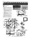
Although unit is weatherproof, guard against water from
higher level runoff and overhangs.
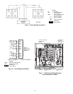
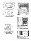
Position unit on roof curb so that the following clearances
are maintained: 7 mm (
1
/
4
-in.) clearance between roof curb and
base rails on each side and duct end of unit; 84 mm (3
5
/
16
-in.)
clearance between roof curb and condenser coil end of unit.
(See Fig. 2, section C-C.)
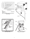
Locate mechanical draft system flue assembly at least
1219 mm (48 in.) from any opening through which combustion
products could enter the building, and at least 1219 mm (48 in.)
from an adjacent building or combustible material. When unit
is located adjacent to public walkways, flue assembly must be
at least 2.13 m (7 ft) above grade.
Flue vent discharge must have a minimum horizontal clear-
ance of 1219 mm (48 in.) from electric and gas meters, gas reg-
ulators, and gas relief equipment.
Flue gas can deteriorate building materials. Orient unit so
that flue gas will not affect building materials.
Adequate combustion-air space must be provided for proper
operation of this equipment. Be sure that installation complies
with all local codes and Section 5.3, Air for Combustion and
Ventilation, NFGC (National Fuel Gas Code), ANSI (Ameri-
can National Standards Institute), latest revision, U.S.A.
Standards.
(Copy continued on page 8.)
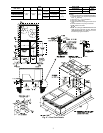
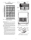
DRAIN PLUG
MAXIMUM ALLOWABLE
DIFFERENCE mm (in.)
A-B B-C A-C
13 (0.5) 25 (1.0) 25 (1.0)
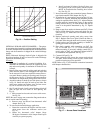
Fig. 3 — Unit Leveling Tolerances
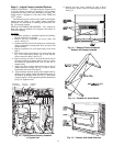
NOTE: Drain plug is shown in factory-installed position.
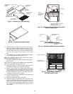
Fig. 4 — Condensate Drain Pan
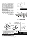
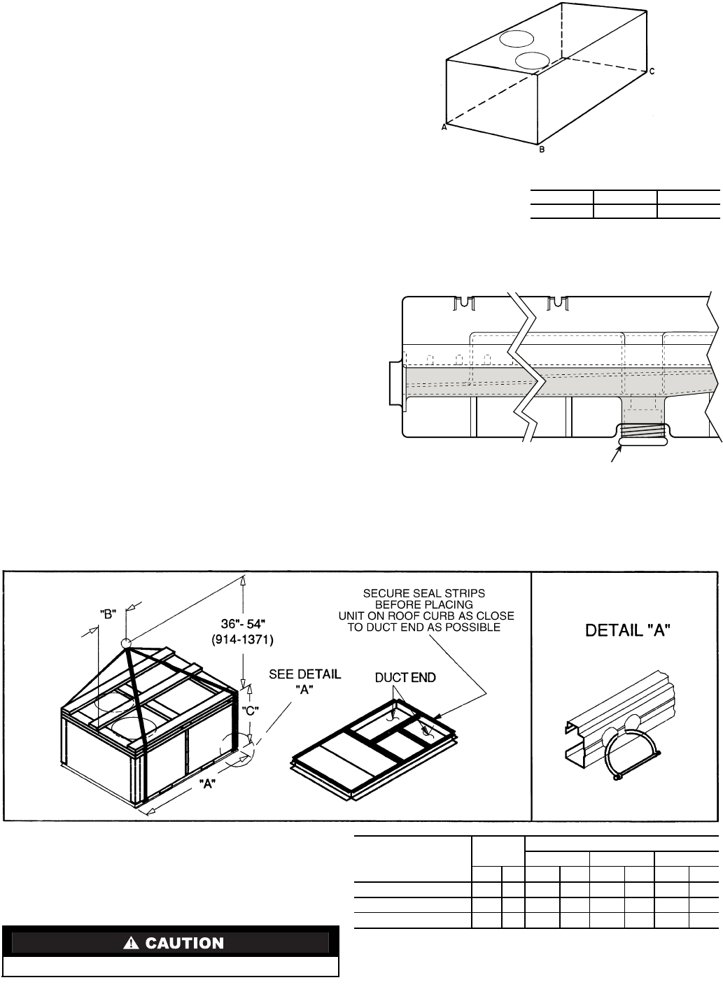
NOTES:
1. Dimension in ( ) is in millimeters.
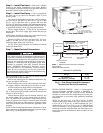
2. Hook rigging shackles through holes in base rail as shown in
detail ‘‘A.’’ Holes in base rails are centered around the unit cen-
ter of gravity. Use wooden top skid when rigging to prevent rig-
ging straps from damaging unit.
3. Weights include base unit without economizer. See Tables 1A
and 1B for economizer weights.
All panels must be in place when rigging.
Fig. 5 — Rigging Details
UNIT
48TF
MAX
WEIGHT
DIMENSIONS
‘‘A’’ ‘‘B’’ ‘‘C’’
lb kg in. mm in. mm in. mm
D/E/F008
870 395 87.38 2219 40.25 1022 41.31 1050
D/E/F012
1035 469 87.38 2219 40.25 1022 49.31 1253
D/E014
1050 476 87.38 2219 40.25 1022 49.31 1253