


19
CO
2
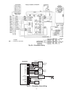
Control Set Up — If a CO
2
sensor is not being used, pro-
ceed to the next section. If a CO
2
sensor is being used, perform
the following:
1. Determine the value at which you want the minimum
position of the dampers to begin opening to allow a great-
er amount of outdoor air to enter. The range is 800 to
1,400 ppm.
2. Locate the CO
2
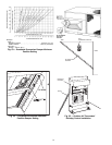
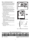
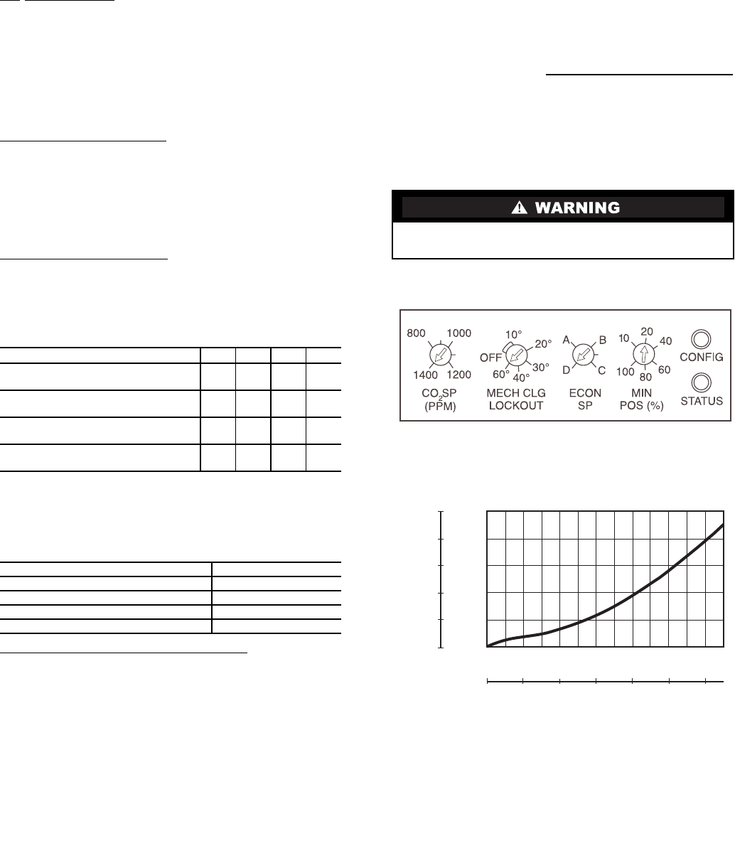
SP (PPM) potentiometer and adjust to the
desired set point. See Fig. 40.
Mechanical Cooling Lockout
— Determine the outdoor-air
temperature at which you want the mechanical cooling (com-
pressors) to be disabled. Locate the mechanical cooling lockout
(MECH CLG LOCKOUT) potentiometer. To disable this fea-
ture, turn the potentiometer counterclockwise (CCW) to the
OFF position. Otherwise, set the value between –12 and 15 C
(10 and 60 F). Mechanical cooling will not operate when the
outdoor air temperature is below this value. See Fig. 40.
Dry Bulb Changeover Set Up
— Determine the dry bulb
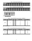
changeover set point from Table 4. The settings are A, B, C and
D. Locate the ECON SP potentiometer and set the dry bulb
changeover set point. See Fig. 40. When the OAT is above this
set point, the damper is limited to minimum position setting.
Table 4 — Changeover Set Points
*Field-installed accessory.
If a potentiometer fails, its setting will default to the values
in Table 5.
Table 5 — Default Potentiometer Settings
Ventilation Air (Minimum Position Set Up)
— If ventilation
air is not required, proceed to Step 5. If ventilation air is re-
quired, perform the following:
1. The indoor fan must be on to set the ventilation air. Either
put the thermostat in the continuous fan mode or jumper
the R and G terminals at the rooftop unit connection
board.
2. Locate the minimum position (MIN POS) potentiometer.
Turn the potentiometer full CCW to fully close the out-
door air dampers. Turn the potentiometer gradually
clockwise (CW) to the desired position. See Fig. 40.
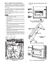
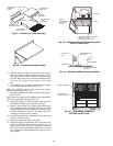
3. Replace the filter access panel. See Fig. 21. Ensure the fil-
ter access panel slides along the tracks and is securely
engaged.
4. Calculate the minimum airflow across the EconoMi$er.
a. Calculate % of outside air using the following
formula.
% Outdoor air through EconoMi$er
b. Multiply total CFM by percentage outdoor air, this
gives outdoor air volume in CFM.
5. Turn on base unit power.
NOTE: The EconoMi$er begins operation three min-
utes after power up.
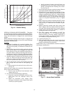
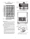
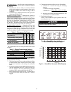
6. See Fig. 41 for barometric relief damper characteristics.
SETTINGS ABCD
Dry Bulb C (°F)
23
(73)
21
(69)
19
(66)
17
(63)
Single Enthalpy* KJ/Kg (Btu/lb)
63
(27)
58
(25)
56
(24)
51
(22)
Differential Temperature* C
(°F, Not Adjustable)
1.1
(2)
1.1
(2)
1.1
(2)
1.1
(2)
Differential Enthalpy* KJ/Kg
(Btu/lb, Not Adjustable)
2
(1)
2
(1)
2
(1)
2
(1)
POTENTIOMETER DEFAULT SETTING
CO
2
SP (PPM)
1,000
MECH CLG LOCKOUT, C (F)
8.3 (47)
ECON SP
D
MIN POS (%)
20
% Outdoor air =
Mixture Temp – Return Air Temp
Outdoor Temp – Return Air Temp
Personal Injury Hazard. Avoid possible injury by keep-
ing fingers away from damper blades.
0
400
800
1200
1600
2000
2400
FLOW (CUBIC FEET/MINUTE)
0.5
0.4
0.3
0.2
0.1
0
STATIC PRESSURE (IN.WG)
PRESSURE DROP (Pa)
FLOW (L/s)
0
200
400
600
800
125
100
75
50
25
0
1000 1200
Fig. 40 — EconoMi$er Control Adjustment
Potentiometers (Factory Settings)
Fig. 41 — EconoMi$er Barometric Relief Capacity