


6
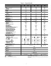
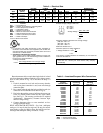
Table 1B — Physical Data (English)
LEGEND *Weight of 356 mm (14-in.) roof curb.
NOTE: The 48TF units have a loss-of-charge (low pressure) switch located in
the liquid line.
UNIT SIZE 48TF 008 012 014
Low Heat (D), Medium Heat (E), High Heat (F) D E F D E F D E
NOMINAL CAPACITY (tons) 6.1 8.3 10.2
OPERATING WEIGHT (lb)
Unit 870 1035 1050
Durablade Economizer 44 44 44
EconoMi$er 62 62 62
Roof Curb* 143 143 143
COMPRESSOR TYPE Hermetic Hermetic Scroll
Quantity 222
Oil (oz) 50 ea 50 ea 54 ea
REFRIGERANT TYPE R-22
Operating Charge (lb-oz)
Circuit 1 4-10 6-13 7-11
Circuit 2 4-11 7- 2 7- 8
CONDENSER COIL Enhanced Copper Tubes, Aluminum Lanced Fins
Rows...Fins/in. 1...17 2...17 2...17
Total Face Area (sq ft) 20.50 20.50 25.00
CONDENSER FAN Propeller Type
Nominal Cfm 6100 6500 6500
Quantity...Diameter (in.) 2...22 2...22 2...22
Motor BkW...Rpm
1
/
4
...930
1
/
4
...930
1
/
4
...930
EVAPORATOR COIL Enhanced Copper Tubes, Aluminum Double-Wavy Fins, Acutrol™ Feed Device
Rows...Fins/in. 3...15 3...15 4...15
Total Face Area (sq ft) 8.0 10.0 11.1
EVAPORATOR FAN Centrifugal Type
Quantity...Size (in.) 1...15 x 15 1...15 x 15 1...15 x 15
Type Drive Belt Belt Belt
Nominal Cfm 2600 3500 4200
Motor Hp 1
1
/
2
23
Maximum Continuous Bhp 2.40 2.40 3.70
Motor Frame Size 56 56 56
Fan Rpm Range 492-700 571-779 717-900
Motor Bearing Type Ball Ball Ball
Maximum Allowable Rpm 1600 1600 1600
Motor Pulley Pitch Diameter Min/Max (in.) 2.4/3.4 2.8/3.8 4.0/5.0
Nominal Motor Shaft Diameter (in.)
5
/
8
5
/
8
7
/
8
Fan Pulley Pitch Diameter (in.) 7.0 7.0 8.0
Nominal Fan Shaft Diameter (in.) ———
Belt, Quantity...Type...Length (in.) 1...A...49 1...A...49 1...A...53
Pulley Center Line Distance (in.) 16.75-19.25 15.85-17.50 15.85-17.50
Speed Change per Full Turn of
Movable Pulley Flange (rpm)
41 41 36
Movable Pulley Maximum Full Turns
From Closed Position
555
Factory Setting 555
Factory Speed Setting (rpm) 492 571 717
Fan Shaft Diameter at Pulley (in.) 111
FURNACE SECTION
Rollout Switch Cutout Temp (F) 195 195 195
Burner Orifice Diameter (in. ...drill size)
Natural Gas — Std .120...31 .120...31 .120...31 .129...30 .120...31 .129...30
Liquid Propane — Alt .096...41 .096...41 .096...41 .102...38 .096...41 .102...38
Thermostat Heat Anticipator Setting (amps)
400 v Stage 1 .14 .14 .14 .14 .14
Stage 2 .14 .20 .20 .20 .20
Gas Input (Btuh) Stage 1 72,000 109,000 136,000 109,000 136,000 150,000 136,000 150,000
‘ 107,000 172,000 204,000 172,000 204,000 224,000 204,000 224,000
Efficiency (Steady State) (%) 80 80 80
Temperature Rise Range (F) 20-50 35-65 45-75 35-65 45-75 40-70 45-75 40-70
Manifold Pressure (in. wg)
Natural Gas — Std 3.5 3.5 3.5
Liquid Propane — Alt 3.5 3.5 3.5
Field Gas Connection Size (in.)
1
/
2
3
/
4
3
/
4
3
/
4
3
/
4
HIGH-PRESSURE SWITCH (psig)
Standard Compressor
Internal Relief (Differential)
450 ± 50 500 ± 50
Cutout 428
Reset (Auto.) 320
LOW-PRESSURE SWITCH (psig)
Cutout 7 ± 3
Reset (Auto.) 22 ± 7
FREEZE PROTECTION THERMOSTAT
Opens (F) 30 ± 5
Closes (F) 45 ± 5
OUTDOOR-AIR INLET SCREENS Cleanable
Quantity...Size (in.)
1...20 x 25 x 1
1...16 x 25 x 1
RETURN-AIR FILTERS Throwaway
Quantity...Size (in.) 4...16 x 20 x 2 4...20 x 20 x 2 4...20 x 20 x 2
Bhp — Brake Horsepower
BkW — Fan Input Watts x Motor Efficiency