


20
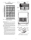
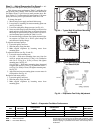
Step 9 — Adjust Evaporator-Fan Speed —
Ad-
just evaporator-fan speed to meet jobsite requirement.
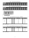
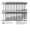
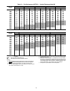
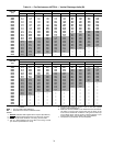
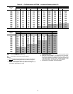
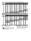
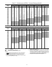
Table 6 shows motor performance. Tables 7 and 8 show fan
rpm at motor pulley settings, Table 9 shows motor efficiencies
and Tables 10 and 11 give accessory static pressure drops. Re-
fer to Tables 12-23 to determine fan speed settings. Fan motor
pulleys are factory set for speed shown in Table 1A or 1B.
To change fan speed:
1. Shut off unit power supply and install lockout tag.
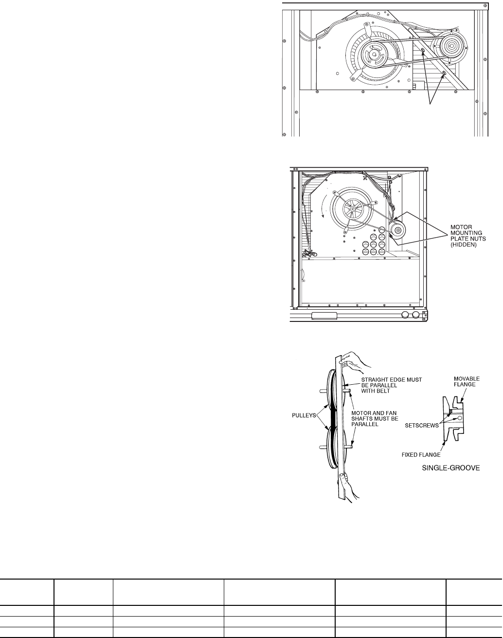
2. Loosen belt by loosening fan motor mounting plate nuts
(see Fig. 42 and 43).
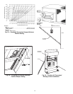
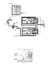
3. Loosen movable pulley flange setscrew (see Fig. 44).
4. Screw movable flange toward fixed flange to increase fan
speed and away from fixed flange to decrease fan speed.
Increasing fan speed increases load on motor. Do not ex-
ceed maximum speed specified in Table 1A or 1B.
5. Set movable flange at nearest flat of pulley hub and tight-
en setscrew (see Table 1A or 1B for speed change for
each full turn of pulley flange).
To align fan and motor pulleys:
1. Loosen fan pulley setscrews.
2. Slide fan pulley along fan shaft.
3. Make angular alignment by loosening motor from
mounting plate.
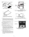
To adjust belt tension (see Fig. 42 and 43):
1. Loosen fan motor mounting nuts.
2. Size 008 — Slide motor mounting plate away from fan
scroll for proper belt tension (13 mm [
1
/
2
-in.] deflection
with 3.6 to 4.5 kg [8 to 10 lbs] of force) and tighten
mounting nuts. See Fig. 42.
Sizes 012,014 — Slide motor mounting plate downward
to tighten belt tension (13 mm [
1
/
2
-in.] deflection with 2.3
to 4.5 kg [5 to 10 lbs] of force) and tighten mounting nuts.
See Fig. 43.
3. Adjust bolt and nut on mounting plate to secure motor in
fixed position. See Fig. 44.
Realign fan and motor pulleys:
1. Loosen fan pulley setscrews.
2. Slide fan pulley along fan shaft.
3. Make angular alignment by loosening motor from
mounting plate.
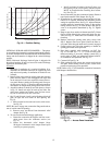
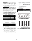
Table 6 — Evaporator-Fan Motor Performance
LEGEND *Extensive motor and electrical testing on these units ensures that
the full range of the motors can be utilized with confidence. Using
your fan motors up to the ratings shown in this table will not result in
nuisance tripping or premature motor failure. Unit warranty will not
be affected.
UNIT
48TF
UNIT RATED
VOLTAGE
MAXIMUM ACCEPTABLE
CONTINUOUS
BkW*
MAXIMUM ACCEPTABLE
CONTINUOUS
BHP*
MAXIMUM ACCEPTABLE
OPERATING
WATTS
MAXIMUM
AMP DRAW
008
400 2.76 2.90 2615 3.6
012
400 2.76 3.70 3313 5.0
014
400 2.76 3.70 3313 5.0
BHP —
Brake Horsepower
BkW —
kW x Motor Efficiency
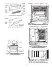
MOTOR MOUNTING
PLATE NUTS
Fig. 42 — Typical Belt-Drive Motor Mounting
for Size 008
Fig. 43 — Typical Belt-Drive Motor Mounting
for Sizes 012,014
Fig. 44 — Evaporator-Fan Pulley Adjustment