


TESTING: Door Locks
There are three basic types:
“Type A” Door Lock Test (Most GMs and some Chryslers)
Probe both of your door lock wires going to the door lock switch usally located in the driver’s
kick panel. Attach the clip end of your test light to a good chassis ground. Using the vehicle’s
door lock controls, activate the lock then the unlock, testing both wires one at a time. If one
of these wires tests (+) positive when lock is pressed and the other tests (+) positive when they
are unlocked, your vehicle has a “Type A” door locking system. Make sure to mark which wire is
lock and unlock. Proceed to Connecting Door Locks, Connecting Door Locks. NOTE: “Type A” and “Type
C” locks will test the same, until you test for ground. Make sure you run both tests before making
your connections.
“Type B” Door Lock Test (Most Imports, some newer Fords)
Probe both of your door lock wires going to the door lock switch usally located in the driver’s
kick panel. Attach the clip end of your test light to +12V. Using the vehicle’s door lock controls,
activate the lock then the unlock testing both wires one at a time. If the test light illuminates
when you probe the lock and the unlock wires your vehicle has a “Type B” door locking system. Make
sure to mark which wire is lock and unlock. Proceed to Connecting Door Locks.
“Type C” Door Lock Test (Most Fords, some Chryslers, GM Trucks)
(Optional part #778 required)
Using your test light probe both the lock and the unlock wires usually located in the driver’s
kick panel. Attach the clip end of your test light to ground probing both wires one at a time while
locking and unlocking the doors with the driver’s side switch (usually the master switch). The
test light should illuminate in both switch positions. Now attach the clip end of your test light
to +12V constant, probe both wires one at a time again. The light should then illuminate again
only in reverse order. This tells you that you have a “Type C” reversing polarity system. Make
sure to mark which wire is lock and unlock. Proceed to Connecting Door Locks.
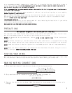
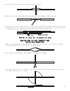
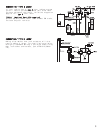
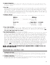
CONNECTING “TYPE B LOCKS”
• If your vehicle has a “Type B” door locking system, connect
the GREEN WITH BLACK STRIPE wire from the 18-pin harness
to the door lock wire. Connect the BROWN WITH BLACK STRIPE
wire to the unlock wire. See diagram below.
“Type B” - Negative type door locks used on most imported
vehicles and some newer Fords.
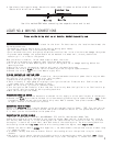
CONNECTING DOOR LOCKS (Optional)
CONNECTING “TYPE A LOCKS”
•If your vehicle has a “Type A” door locking system, connect
the BROWN WITH BLACK STRIPE wire from the 18-pin harness
to the door lock wire. Connect the GREEN WITH BLACK STRIPE
wire to the unlock wire. See diagram below.
“Type A” - Positive type door locks used on most GM, some
Chrysler vehicles.
8
BROWN/BLACK
LOCK
UNLOCK
GREEN/BLACK
GREEN/BLACK
LOCK
UNLOCK
BROWN/BLACK
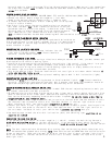
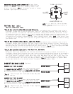
87a
TO DOME LIGHT CIRCUIT
+12 VOLT
FUSED AT
5 AMPS
(-) VIOLET
FROM ALARM
(+) OR (-)
DEPENDING ON DOOR TYPE
NOTE: If (+) positive, fuse at 20 amps,
if (-) negative connect to pin 30 to a
chassis ground.
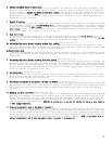
CONNECTING THE DOME LIGHT SUPERVISION Optional Relay
Connect the violet wire from the control module wiring
harness to the done light wire, normally found in the
driver's kick panel. NOTE: A relay must be used to connect
the dome light supervision function,