


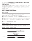
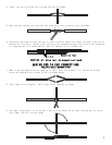
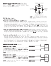
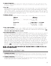

4. Use electrical tape to wrap, be sure to cover about 2 inches on either side of connection.
Secure with wire ties as shown.
Use this method ONLY when connecting two separate wires end to end.
Wire Tie
Electrical Tape
Wire Tie
LOCATING & MAKING CONNECTIONS
5
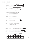
Please see the wiring chart on our website, www.bulldogsecurity.com.
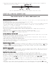
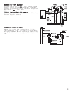
MOUNTING AND CONNECTING THE SIREN
Select a location under the vehicle's hood for the siren. For best results, the location should meet the
following conditions.
•The mounting location should be solid and have no moving parts nearby.
•For the loudest sound, the siren should point down.
•The siren should not point straight up as moisture could collect in the siren horn and damage the system.
•To prevent water damage, the system should not be mounted in a wheel well, directly behind the
radiator grill, or close to the ground.
Once you select a location, follow these steps to mount the siren:
1.Using the siren base as a template, mark the three mounting holes.
2.Drill an 1/8" hole at each mounting hole location, taking care not to damage anything behind the
mounting surface.
3.Secure the siren to the mounting location with two of the mounting screws.
4.Connect the siren's black wire to the third mounting screw, suing the spade connector.
5.Connect the siren's red wire to the module's grey wire.
FINDING CONSTANT AND IGNITION POWER
Your system operates from 12 volts. In addition, the system needs a source of power that is only on when
the ignition is on (usually referred to as ignition power).
1.Locate the wires going to your ignition switch.
2.There is usually a large gauge wire going to your ignition switch. Probe the wire. Confirm that the
light comes on or the meter indicates 12 volts.
3.Mark this wire with its function (Constant Power).
4.Turn the ignition ON. Probe for a wire that has 12 volts only when the ignition is on. Confirm this by
turning the ignition on and off while probing each wire.
5.Mark this wire (Ignition Power).
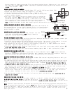
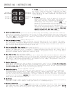
CONNECTING POWER AND GROUND
1.Connect the red wire from the harness to a constant 12 volt supply or at the positive post of the battery.
2.Connect the black wire from the harness to a clean chassis ground using the spade terminal. TEST: Press
transmitter button #1 and the siren should chirp once. Wait 5 seconds, then press transmitter button
#1 again, and the siren should chirp twice.
CONNECTING IGNITION POWER
Connect the red/black wire from the harness to the wire marked "Ignition Power". TEST: Turn the ignition
switch to the ON or accessory position and then press transmitter button #1, the system should not arm.
If it does, you are not connected to the power wire.
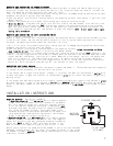
CONNECTING THE STARTER DISABLE
Optional in 5002 Models, Use Part #30-ARB(Model 757) and Pro 1000 Harness (Model 769)
Locate the cranking wire at the base of the steering column. When testing, cranking wire will show 12
volt DC only when the key is in the cranking position. Once located, cur the wire in two. Try to crank
the engine, it should not crank. Next, mark both ends of the cranking wire. The wire running back into
the steering column mark key side, and the wire running toward the engine, mark engine side.
1.Connect the control module orange wire negative (-) out when armed to the optional starter disable relay
(-) negative input.
2.To connect the Key Side and the Starter Side of the cranking wire to the optional relay for starter
disable.
3.Use a wire tire to secure the starter disable relay to a non-moving part under the dash. TEST: Press
transmitter button #1 to arm the system and then try to start the engine, it should not start. Press