


7
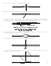
MOUNTING AND CONNECTING THE OVERRIDE SWITCH
Select a location for the override switch. You should be able to reach the switch when sitting in
the driver's seat, but the switch should be hard to find. A typical mounting location is under the
dash. The mounting surface should be less than 1/8" thick.
1.Drill a 5/16" hole in the mounting surface, taking care not to damage anything behind the surface.
2.Remove the switch's top nut and lock washer.
3.Push the switch into the hole from the back of the mounting surface. Then secure it with the lock
washer and not.
4.Connect the ground wire to a metal vehicle body part using an existing screw.
5.Override Switch - Plug override switch into the left side of the main header (this switch is the
same used with anti-carjacking) TEST: Violate any zone on the alarm causing the siren to sound.
Open the vehicle door, place ignition key to "ON" position, then press the override switch. The
siren should silence and you will now be able to start the engine. NOTE: A door must remain open
during this procedure.
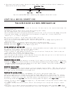
MOUNTING AND CONNECTING THE ANTI-CARJACKING SWITCH
Only found on 7002 models
Select a location for the anti-carjacking switch. You should be able to reach the switch when sitting
in the driver's seat, but the switch should be hard to find. A typical mounting location is under
the dash, the mounting surface should be less than 1/8" thick.
1.Drill a 1/4" hole in the mounting surface, taking care not to damage anything behind the surface.
2.Remove the switch's top nut and lock washer.
3.Push the switch into the hole from the back of the mounting surface. Align the switch so ON is
away from the driver. Then secure it with the lock washer andnut.
4.Connect the ground with to a metal vehicle body part using an existing screw. TEST: Close all the
doors, flip the toggle switch to the ON or forward position and start the vehicle. Open and close
a door and wait one minute, the siren will sound. When the siren sounds, turn off the engine and
then try to restart it. The engine should not start. To return the system to normal operation,
turn off the ignition switch, flip the toggle switch to OFF or to the rear and press transmitter
button #1. The siren should stop and you will not be able to start the engine.
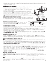
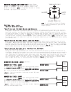
CONNECTING ADDITIONAL SENSORS
Follow the instructions that come with the sensor to mount and power it. The system requires a negative
(-) output on the accessory for activation of the alarm.
If the sensor has a single alarm output, connect it to either the main wiring harness's yellow wire
to have the sensor trigger the alarm or to the harness's green wire to have the sensor trigger only
warning chirps.
If the sensor has both warning and alert triggers, connect the warning trigger to the harness's green
wire and the alert trigger to the harness's yellow wire CAUTION: When adding more than one shock
sensor or perimeter sensor on the same input trip, you must add a 1 amp diode to the output of each
sensor.
INSTALLATION INSTRUCTIONS
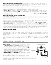
NEGATIVE OUTPUTS - See wiring schematic
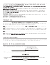
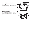
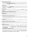
1.Negative output #2 - the white/red wire is used to operate
a ower trunk release power sun roof, window roll-up module,
etc. This negative output will pulse for one half second,
or for as long as transmitter button #2 is depressed. NOTE:
A 30 amp relay must be used since this negative output is
only rated for 200mA (1/5 amp). Since most power trunk
releases are positive controlled and draw 5 to 6 amps, this
relay handles the load and also can convert the release
signal from negative to positive polarity.
2.Negative output #3 - the white/yellow wire is used to operate
the car starter, window roll-up module, etc. The negative
output will pulse for one half second by pressing transmitter
button #3. NOTE: A SPST or SPDT relay must be used if you
want to convert the negative signal to positive or if the
87a
TO FACTORY TRUNK WIRE
+12 VOLT FUSED
AT 20 AMPS
WHITE/RED
FROM ALARM
device you're controlling draws more than 200mA. If you're not sure how much
amperage is being drawn, add the relay. This negative output is only rated
for 200mA (1/5 amp). CAUTION: Overloading these outputs is not considered
a warranty related repair.