


10
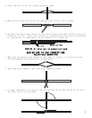
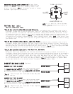
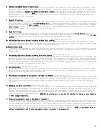
WIRING DIAGRAMS
FIGURE 1
1. Red (+) 12 volt constant
2. Black chassis ground
3. Grey (+) siren output
4. White/Red button #2 / channel #3 (-) output: trunk
pop, window rollup, etc. 200mA max
5. White/Yellow button #3 / channel #2 (-) output: remote
start, etc. 200 mA max (see figure 7)
6. Brown/Black (+) unlock or (-) lock output
7. Green/Black (+) lock or (-) unlock output
8. Orange (-) output when armed: starter disable, etc
(see fig. 9)
9. Brown (+) parking light output
10. Open
11. Green (-) shock sensor input (minor): warn away /
10 second delay after arming
12. Yellow (+) shock sensor input (major): triggers
alarm / 10 second delay after arming
13. Black/Blue (+) door pin input / 20 second delay after arming
14. Black/Yellow (-) door pin input / 20 second delay after arming
15. Violet (-) output dome light supervision 300mA max (see fig. 6)
16. Red/Black (+) 12 volt ignition sense input
L
8 7 6 5 4 3 2 1
16 15 14 13 12 11 9 R
RED
BLACK