


6
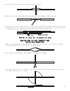
button #1 again to disarm the system. This time the engine should start. Make sure all your connections
are electrically sound. NOTE: A 1N4001 diode must be used when connecting more than one device to the
orange wire as shown.
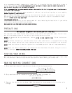
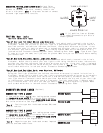
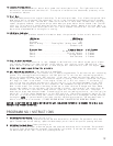
STARTER DISABLE RELAY AND HARNESS
Optional in 5002 Models use Part #30-ARB (Model 757) and Pro 1000 harness (Model 769)
1.Connect the control module orange wire negative (-) out when
armed to the optional starter disable relay (-) negative input.
2.To connect Key Side and Starter Side of cranking wire to the optional
relay for starter disable,
3.Use a wire tie to secure the starter disable relay to a non-moving
part under the dash. TEST: Press transmitter button #1 to arm the
system and then try to start the engine, it should not start. Press
button #1 again to disarm the system. This time the engine should
start. Make sure all your connections are electrically sound.
NOTE: A 1N4001 diode must be used when connecting more than one device to the orange wire as shown.
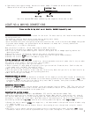
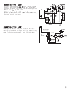
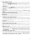
INSTALLING THE FLASHING LED STATUS INDICATOR
The LED indicator installs inside your vehicle and should be installed as
high as possible and in view from all windows. Drill a 1/4" mounting hole
in the dash panel or use the supplied mounting bracket to hold the LED
status indicator in place.
CONNECTING THE LED STATUS INDICATOR
1.Insert the blue plug of the LED status indicator into the
right side of the main header. TEST: Press transmitter
button #1, the LED should flash.
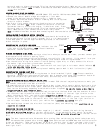
FINDING THE PARKING LIGHT WIRE
To have the parking lights flash during a violation or when you use the car finder, you must connect your
alarm system to the vehicle's parking lights.
1.Locate the wire harness going from the back of your vehicle's light control. If the control is on your
vehicle's steering column, the harness probably joins several other wiring harnesses.
2.Use the vehicle's wiring color code to find the parking lights wire, or simply connect this wire to
the marker light wire ususlly found under the hood.
3.Turn on the parking lights. Touch one lead from a 12 volt test light or volt meter should indicate 12
volts only when the lights are on.
4.After you locate the light wire, use a piece of masking tape to mark it with its function (lights).
CONNECTING THE PARKING LIGHT WIRE
1.Connect the brown wire from the wiring harness to the wire marked "lights". TEST: Press transmitter
button #1, the parking lights should flash once, wait 5 seconds, then press the transmitter button #1
again and the parking lights should flash twice, and then stay on for 30 seconds.
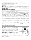
DETERMINING YOUR VEHICLE'S DOOR PIN SWITCH TYPE
NOTE: For your alarm system's passive arming and in model 7002 the anti-carjacking feature to work, you
must connect the alarm to the door pin switch.
1.On some vehicles this wire might also be called a door trigger and is usually behind the driver's kick
panel or behind the driver's door panel. Some vehicles have logic controlled dome and courtesy lights
that turn on differently depending on which vehicle door is opened. Be sure to locate a wire that is
triggered from all your vehicle's doors.
2.Touch your meter or test light's positive lead to a point on the fuse block that has constant 12 volts.
Use the other lead to probe the control wire. Then open the door. If the test light turns on or the
meter indicates 12 volts, your vehicle has a negative (-) switch door pin.
3.Connect your meter or test light's negative lead to a good solid chassis ground. Use the positive
lead or other lead probe to the control wire. Then open the door. If the test light turns on or
the volt meter indicates 12 volts, your vehicle has a positive (+) switch door pin.
4.Use masking tape to mark the wire with its function (door) and switching type, positive (+) or
negative (-) switch.
CONNECTING THE DOOR PIN SWITCH
If you marked the door switch "wire door negative (-) switch", connect the main wiring harness's
black wire with yellow stripe to the door switch wire. If you marked the door switch "wire door
positive (+) switch", connect the main wiring harness's black wire with blue stripe to the door switch
wire.
NOTE: The door inputs activate 20 seconds after arming. Door switch testing should take place only
after 20 seconds have elapsed after arming. NOTE: Some vehicles such as HONDA have door switch isolation
diodes on each door. These vehicles must be wired at the wire that triggers the dome light circuit
after the diodes. If the door switch wires are difficult to reach, connect the input wire to the
dome light itself.
BLUE PLUG
ON THE RIGHT
OF MODULE
LED
INDICATOR
GROUND
OVERRIDE
SWITCH
WHITE PLUG
ON THE LEFT
OF MODULE
87A
85
86
87
30
ORANGE
TO STARTER
IGNITION
CRANKING
WIRE