


CT-5000 Installation Guide P.5
WIRES at the IGNITION switch, this will compromise the OEM electrical
system.
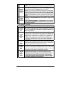
E
ORANGE
(+) 30 A
Accessories
output
This wire is for powering the heater blower motor. It is usually classed as an
ACC. (no power in the CRANK position.) if it tests as an IGNITION (power in the
crank pos.) then power it as an
IGNITION (5th relay, or extra fuse).
Warning: some vehicles have more than one ACC wire at the IGNITION
switch for powering the heater blower motor. Use the 5th relay (pin F) and
extra relays to power up any extra ACC. wires if necessary. DO NOT JUMP
WIRES at the IGNITION switch, this will compromise the OEM electrical
system.
F
GREEN
(+) 30 A 5
th
relay output
This high-current output can be used to power a 2
nd
IGNITION or a 2
nd
ACCESSORY or a 2
nd
STARTER WIRE. See jumper settings on page 16 for
correct output.
Additional IGNITIONS, ACCESSORIES, or STARTER WIRES must use external
relays. DO NOT JUMP WIRES at the IGNITION switch, this will compromise
the OEM electrical system.
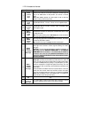
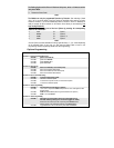
5-Pin Secondary Harness
Wire Description
1
BLACK
(–) Chassis
ground
input
This wire must be connected to bare, unpainted metal (the Chassis or true
Body ground). It is preferable to use a factory ground bolt rather than a self-
tapping screw. Screws tend to get loose or rusted over time and can
cause erratic problems.
2
PURPLE
(AC)
Tachometer
input
This wire tells the Module if the Engine is running or not. It requires at least
1.8 volts (AC) and 1.5 Hz (or faster) at idle. Common Tach references are:
the negative side of an injector, the negative side of an Ignition Coil,
Camshaft sensor, Crankshaft sensor or the Engine Control Module (ECM).
NOTE: A Tach signal that is too low will cause the Module to “over
crank” and a Tach signal that is too high will cause the Module to
“under crank”.
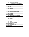
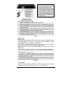
3
GRAY
(-) Hood
Switch
input
Connect this wire to the Hood Pin-switch supplied. This input will disable or
shut down the Remote Starter when the Hood is opened. It is also used for
programming and therefore it is essential that it is installed.
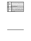
4
ORANGE
(+) Brake
Switch
input
This wire must be connected to the Brake Light switch of the vehicle. The
wire should be +12 V only while the Brake Pedal is pressed. This input will
shut down the Remote Starter if the Brake Pedal is pressed. It is also used
for programming and therefore it is essential that it is installed.
5
YELLOW
+12 V
Parking
Light
output
This wire provides a +12 V output (15 A max.) and must be connected to
the Parking Light wire that tests +12 V when the Parking lights are
ON.
Note: Ensure that the voltage does not vary when the dimmer control
switch is turned up or down. If this is the case, it is not the right wire.
There is also a negative Parking Light output. Only one of these
two different outputs needs to be connected.