


CT-5000 Installation Guide P.15
Away. A medium “tap” should trigger the Warn Away. A hard “tap”
should trigger the Alarm.
• All vehicles are different and therefore transmit shock level differently, if
you are unable to set both zones to your satisfaction, referrer to p.12
(Function 4 – Shock Sense / Warn Away
• ) to disable the appropriate zone(s).
• When the Engine is running after remote start the Shock Sensor will not
trigger an Alarm condition, although it will still produce warning chirps if
Warn-away is enabled.
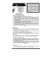
8. Two- g
button mut
Module.
ehicle
Sta e Disarm: When the vehicle is in an alarm condition, pressing the
UNLOCK
es the Siren, pressing the UNLOCK button a second time disarms the
9. Starter Kill option: Sit inside the vehicle with all the Doors closed. Arm the v
and then try to start the vehicle with the key –it should not start. If the vehicle starts,
rewire the starter kill so it functions properly.
Closing
Use tie nd keep the wiring away from any
ng ount all switches in
sible locations where they do not risk getting kicked or hit accidentally. Any
S
START)
a high-current programmable 5th relay onboard that
Accessory, or Start wire.
nction. In order to
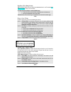
10. Valet Mode: Make sure the Module is able to enter and exit Valet Mode properly.
When setting the Module into Valet mode, the Starter Kill function is disabled, when
pressing
LOCK the Doors will lock but the Starter Kill will not be activated. (Refer to
User Guide for more information on Valet Mode).
11. Idle Mode: Make sure the vehicle properly goes into Idle Mode.
Up
-wraps or screws to properly secure the Module a
movi parts such as the Parking Brakes or Steering Column Shafts. M
good and acces
under hood wiring should be split loomed and tie strapped away from moving parts and heat
sources.
Always make all your connections before plugging in the Module. Keep in mind to plug the
fuses as the last step before the initial powering of the Module. Be sure to test all
functions properly before closing up the installation.
Make sure the Warning Label is applied on a visible place under the Hood.
Most comebacks are the result of misunderstandings about how a product works or performs.
Take the time to properly explain all functions and features to the customers before they
leave the premises. Doing this will save time and money.
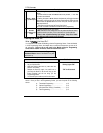
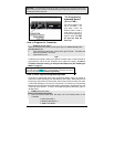
upplementary Information
Fifth Relay Output (2
nd
IGN or 2
nd
ACC or 2
nd
This Remote Starter is equipped with
can be used to power a second Ignition,
The Unit uses a series of jumpers; each set of jumper pins represents a fu
activate any one of the three possible 2nd outputs, you must place the jumper (supplied) on
one of the three sets of pins and simply connect the 14 AWG wire to the second
IGN or ACC or
START
wire of the vehicle.