


CT-5000 Installation Guide P.23
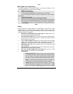
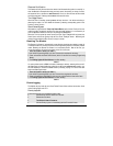
Problem: You need to power Multiple Ignition wires to remote start the vehicle, but your module
only has one Ignition output available.
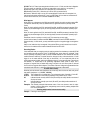
Solution: You will need to add a second ignition relay to power the second ignition wire.
(Jumping Ignition 1 to Ignition 2 is NEVER recommended. Always use a relay.
The vehicle circuits are Isolated for a reason, the wiring of the remote star
module should reflect this.)
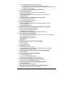
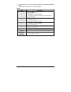
The relay connections:
85: Connects in parallel to the Ignition 1 output from the remote start module. This
becomes the positive side of the coil.
86: Connects to the Ground Out when Running wire from the remote start module. This
becomes the negative side of the coil.
87: Connected to a Fused +12 Volts source, that is capable of supplying power for the
vehicle's second ignition wire. This becomes the source of power for the 2nd ignition
wire.
87A: No connection. This terminal is not used in this application.
30: Connects to the vehicle's second ignition wire. This becomes the output of the 2
nd
ignition relay.
Comments: The relay is only energized when the vehicle is running by remote start. When started
with the Key, the relay is not energized and the integrity of the stock system has been preserved.
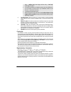
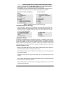
Isolation:
Example: Isolating a Park light output
Problem: Some vehicle circuits need to be isolated from feedback. In some cases, when a
vehicle is remote started, feed back occurs on a circuit, and powers another device or
switch, that was not intended to be powered during the remote starts. The following
example will be a Positive (+) Park Light circuit that feeds back and activates the
windshield wipers during remote starts.
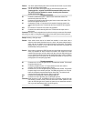
Solution: When power is applied to the OEM Park light wire it back feeds through the park light
switch, and activates the wipers. Where the connection was made from the start
modules' Park light output, and the vehicle's park light circuit, the OEM park light wire
is cut to isolate the park light switch and the actual parking lights. A Relay is added to
the park light circuit so that power from the remote start module is only sent to the
parking lights and not the parking light switch.
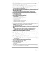
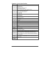
The relay connections:
85: Connects to the +12 Volt Park light output from the remote start module. This becomes
the positive side of the coil.
86: Connects to a Negative source. i.e. The spot where the remote start module is
grounded. This becomes the negative side of the coil.
87: Connects to the +12 Volt Park light output from the remote start module. This becomes
the power supply for the vehicle's park lights. The OEM park light wire is cut. The side
that is still connected to the switch becomes the “Switch Side”. The side that is still
connected to the Parking lights becomes “Parking Lights Side”.
87A: Connects to the “Switch Side” of the cut OEM park light wire.
30: Connects to the “Park Light Side” of the cut OEM park light wire.
Comments: When the relay is at rest, the OEM Park light wire is connected ( through 87A & 30)
and allowed to operate normally. When the remote start module powers the Park
lights, the OEM park light wire is opened, and power from the remote start module is
sent only to the actual Parking Lights ( from 87 through 30).
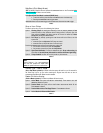
Inversion: