


CT-5000 Installation Guide P.3
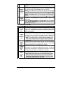
1 – six-pin 14 AWG Harness
(Ignition Harness)
1 – five-pin 18 AWG Harness (Main
Harness)
1 – twelve-pin 22 AWG Harness
(Accessories Harness)
1 – two-pin 22 AWG Harness
(Accessories Harness)
1 – five-pin Harness (Data Port Harness)
1 – Parts bag: a Hood Pin-switch, a
connector, wires and a warning label
1 – User Guide.
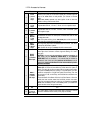
Installation Tools:
Here is a list of basic tools and supplies you will need to test and install safely.
• Digital Multi Meter (DMM), Computer safe logic probe, Fused jumper wire, Neon 'trouble' light
that is carpet safe, Fender protector, Carpet protector
• Soldering Iron, solder, electrical tape, wire tie straps, split loom, diodes, resistors, relays
• Wire cutters, Wire strippers, Wire crimpers, Needle Nose Pliers
• Sharp knife, Panel poppers, Various Screw drivers
• Socket set, Wrench set, Drill with Drill Bits, Coat hanger (for fishing wires through the fire
wall),
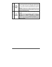
INDUSTRY CANADA USER NOTICE (Canada):
Operation is subject to the following two conditions: (1) this device may not cause
interference, and (2) this device must accept any interference, including interference that may
cause undesired operation of the device.
To reduce potential radio interference to other users, the antenna type and its gain should be
so chosen that the equivalent isotropically radiated power (EIRP) is not more than that
required for successful communication".
FCC USER NOTICE (U.S.A.):
The manufacturer is not responsible for any radio or TV interference caused by unauthorized
modifications to this equipment. Such modifications could void the user’s authority to operate
the equipment.
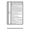
Before You Get
Started
…
♦ On vehicles with a manual Transmission,
always ensure that all Doors will get the Unit out
of Ready Mode. Switch the wire used so that it
is triggered by all Doors.
♦ Make sure that the Parking Brake and Door
Switch contacts work properly.
♦ When working on a vehicle, always leave a
window open.
♦ Never leave the keys in the car. Leave them
on a workbench with a window rolled down.
♦ Remove courtesy light fuse, if possible, to
prevent battery drain.
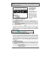
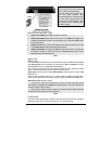
♦ The Programming Assistance Button
(A.k.a. PAB.)
The PAB is mounted on the side of the Unit.
This push button mimics the Hood-Pin switch in
order to avoid having to get out of the vehicle
and pressing the Hood-Pin switch. The PAB will
work
only when the Hood is up.
♦ Never ground the control unit to the vehicle’s
steering column.
♦ Inspect vehicle for any body damage or
electrical problems
♦ Always solder and tape all connections.
♦ Keep the Transceiver away from other types
of antennas (GPS/Onstar).
♦ Never install the control unit where it could
interfere with normal operation or obstruct
service technicians.
♦ Always use a grommet when running wires
into the Engine compartment. Never run wires
through bare or sharp metal.
♦ Do not disconnect the battery on vehicles
equipped with air bags and anti-theft radios.
♦ Make sure that all the switches and controls
operate properly.
♦ Verify that the vehicle starts and idles properly.