


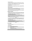
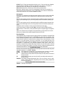

P.22 Installation Guide CT-5000
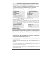
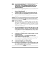
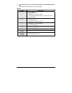
85 & 86: The Coil. These inputs energize the coil when one is +12 Volts, and the other is Negative.
They are usually non-polarized, so it does not matter which one is positive (+) or negative (-).
87: Normally Open ( N/O). When the coil is energized, 87 is connected to 30.
87A: Normally Closed ( N/C ). When the coil is at rest, 87A is connected to 30.
30: Common. When the relay is at rest, 30 is connected to 87A, when the coil is energized, it is
then moved and makes contact with 87. (note: in a SPDT relay, 30 can never be connected to 87
and 87A at the same time, 30 is connected to either 87 OR 87A)
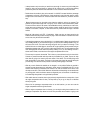
What happens:
When there is no voltage across the COIL (terminals 85 and 86), the relay's movable contact ARM
(connected to terminal 30) is held, by SPRING tension, against terminal 87a (normally closed
circuit).
When 12 volts is applied to the COIL (terminals 85 and 86), the ARM (connected to terminal 30) is
pulled in by the electromagnet (COIL) so that it physically connects to terminal 87 (normally open
circuit)
When 12 volts is applied to the COIL (terminals 85 and 86), the ARM (connected to terminal 30) is
pulled in by the electromagnet (COIL) so that it physically connects to terminal 87 (normally open
circuit)
Remember, there is no polarity on a relay’s coil. This means that you may apply
positive from the battery to either terminal 85 OR 86, and then Ground the OTHER terminal to
activate the relay. In other words, you may used either a positive or negative trigger to energize the
relay.
Keep in mind, when the relay is energized, if the positive OR the ground connection on the coil is
broken, the arm switches the connection between 30 back from 87 to 87a.
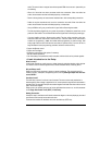
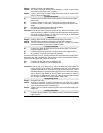
Quenching Diodes:
It was said earlier that you energize a relay by applying positive from the battery to either 85 OR 86
and grounding the other terminal. This is not absolutely true, some relays are “polarized” if they
have a quenching/ suppression diode (A diode installed between the coil terminals 85 and 86,
could be internal or external). To activate the coil on this type of relay, make sure that the +12 Volts
trigger is on the same terminal of the relay as the Anode (+ or non striped side) side of the
quenching/suppression diode, and that the Negative trigger is on the same terminal of the relay as
the cathode (- or striped side) of the quenching/ suppression diode. When a relay’s coil is
energized, a magnetic field is created and energy is stored in the coil. When power is removed
from the coil, the magnetic field collapses. This causes a Reverse Voltage to be generated and can
sometimes reach 200 volts. A quenching diode absorbs this reverse voltage spike.
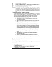
A closer look at a relay:
Now that you know what the main inscriptions are on the relay, take a look on the side, and you will
see another inscriptions: i.e. ( 12 VDV , 40/ 30 A)
12 VDC: This indicates the coil voltage rating. For an Automotive relay, it's usually 12 Volts DC.
40/ 30 A: This indicates the current carrying capability of the contacts 30, 87, & 87A.
40: Indicates that the normally closed circuit (30 and 87a) can safely handle a maximum of
40 amps of current.
30: indicates that the normally open circuit (30 and 87) can safely handle a maximum of
30 amps of current.
Examples: The following examples demonstrate some of the most common uses for relays.
isolation, inversion, interruption, strengthening current, and for powering multiple wires
from one source SAFELY.
Powering multiple wires from one source safely:
Example: Powering a second Ignition