


SYSTEM PROGRAMMING - Menu 1
SYSTEM PROGRAMMING - Menu 1
PAGE 4
PAGE 5
80 SERIES
80 SERIES
INSTALL MANUAL
INSTALL MANUAL
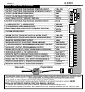
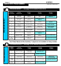
QUICK VIEW WIRE DIAGRAM
MANUAL TRANSMISSION MODELS
1
2
3
1
2
3
1
2
3
4
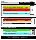
THERMISTOR/ INPUT TRIGGER TO START
Position 1 or Position 2
BLACK**
GREEN**
BLUE**
GREEN
BLUE
N/A*
RED
BLACK
WHT/VIOLET
RED**
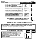
BYPASS MODULE DATA COMMUNICATION PORT
***FOR USE WITH COMPATIBLE BYPASS MODULES ONLY***
1
2
3
4
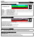
SELECTABLE PARK LIGHT OUTPUT
*****YOU MUST INSTALL A “M” SERIES REMOTE START WHEN INSTALLING ON A
MANUAL TRANSMISSION VEHICLE*****
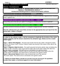
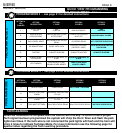
Connect the following wires for manual transmission vehicles:
MANUAL TRANSMISSION
CLUTCH BYPASS
BLK/WHTPARK BRAKE INPUT FOR MANUAL TRANSMISSIONS
PURPLEPOSITIVE DOOR PIN INPUT (ALARMS AND MANUAL ONLY)
GREENNEGATIVE DOOR PIN INPUT (ALARMS AND MANUAL ONLY)
Connect this wire to the door pin switch if it changes to 12volts when the door is opened.*
Connect this wire to the door pin switch if it changes to Negative when the door is opened.*
*Test the vehicles door pin circuit then connect to the appropriate door pin input from the
remote start. (Green or Purple)
Connect this wire to the vehicles Park Brake Switch. The wire should test negative when the park
brake is applied only.
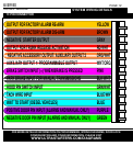
GROUND OUTPUT FOR ADDITIONAL SENSOR (-)
FULL TRIGGER FOR ALARM MODELS (-)
PRE-WARN TRIGGER FOR ALARM MODELS (-)
OUTPUT TO ACTIVATE DOOR LOCK CIRCUIT (-)
OUTPUT TO ACTIVATE DOOR UNLOCK CIRCUIT (-)
OUTPUT FOR VOLTAGE INVERTER*
12VOLT OUTPUT FOR BYPASS MODULE
GROUND OUTPUT FOR BYPASS MODULE
(-) WHILE RUNNING OUTPUT (BYPASS TURN ON)
12VOLT OUTPUT FOR ADDITIONAL SENSORS (+)
* THE CENTRE PIN OF THE KEYLESS CONNECTOR IS LOW CURRENT AND IS DESIGNED
TO SUPPLY POWER TO DOOR LOCK MODULES (DO NOT CONNECT TO RELAYS)
OVERLOADING THIS OUTPUT WILL DAMAGE THE MODULE!
**THIS CONNECTOR IS USED FOR ALARM MODELS ONLY.
*** FOR USE WITH COMPATIBLE BYPASS MODULES ONLY.
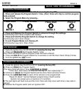
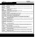
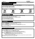
BY DEFAULT THE SYSTEM COMES WITH THE PARK
LIGHT JUMPER SET FOR POSITIVE PARK LIGHT
OUTPUT. TO CHANGE THE SYSTEM TO A NEGATIVE
PARK LIGHT OUTPUT, PLACE THE JUMPER IN THE
NEGATIVE PARK LIGHT POSITION SHOWN IN THE
DIAGRAM. (Position 2)
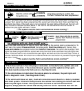
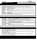
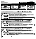
In order for the vehicle to start, it will be necessary to duplicate the function of the clutch
switch. Carefully test the wires to determine the activation type. Below are the 4 clutch
switch types.
Type 1 - Starter Wire Bypass - The start wire travels form the key switch through the clutch
switch to the starter motor. Connect Starter Output wire directly to the starter motor side of the
clutch switch.
Type 2 - Negative (High Current) - This switch grounds the factory starter relay and allows the
vehicle to start. Connect a relay to ground the output side of the clutch switch wire when the
remote starter is activated. The starter wire is connected at the ignition switch.
Type 3 - Connect Switch - Install a relay to connect the two wires at the switch when the
remote starter is activated. The starter wire is connected at the ignition switch.
Type 4 - Disconnect Switch Install a relay to disconnect one of the wires at
the clutch switch. The starter wire is connected at the ignition switch.
***Testing is critical! Never connect to a circuit if you are not sure of it’s operation.
Contact your dealer or technical support for more information.***
POSITIVE
PARK LIGHT
NEGATIVE
PARK LIGHT