


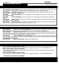
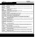
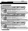

13 PIN CONNECTOR
1-YELLOW Re-arm(-) (Programmable)
Supplies one .75 second pulse when locked and one .75 second pulse after remote start shutdown. Factory
alarm re-arm/ RAP shutdown.
2-BROWN Dis-arm(-)
Supplies one .75 second pulse when the unlock button is pressed and one .75 second pulse before remote
start activation. For factory alarm dis-arm/ “wake up”.
3-GRAY (-) Start/ Crank
Supplies a ground output at the same time as the positive starter output.
4-RED/WHITE Trunk Release(-) (Programmable)
Output will activate when the Unlock button is held for at least 3 seconds. The output will stay on for 5 seconds
or until the button is released
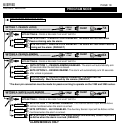
5- ORG/WHT 2nd Acc (-) / Auxiliary Output 2 (Programmable)
Ground output at the same time as the primary Accessory. output. This output can be programmed to activate
as and auxiliary output when the unlock and start buttons are held.
6- WHT/VIOLET Auxiliary Output 1/ Programmable Output
Auxiliary output when the # button is held. Programmable to (-) Ignition/ Car Finder and Dome Light
Supervision with Car Finder. (Car Finder and Auxiliary 1 are not available on 2way models)
7- PINK Brake Switch input (+)
This wire must be connected to the wire at the brake switch that changes to 12volts when the brake is pressed.
*Connect to door pin for Passive Arming on 1280 and 3285.
8- BLACK/WHT Park Brake Input (-)
On manual transmission models this wire must be connected to the vehicles park brake wire. Never install a
automatic remote start in a manual vehicle!
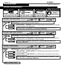
9- GREEN/WHT Hood Pin Input (-)
Connect this wire to the supplied hood pin switch. If ground is detected on this input the remote starter will not
activate.
10- BLUE/WHT Tach Wire Input (A/C)
This wire is used to to detect when the vehicle has started. The Tach source is typically taken from a fuel
injector, coil, coil pack or crank position sensor. The Tach wire is generally found as the opposite from the
common wire at the coil or fuel injector.
11- BLUE Wait to Start Input (+ or -) (Programmable)
On diesel vehicles connect this wire to the wait to start or glow plug wire. The system will wait for the input to
turn off then remote start. A start delay may also be programmed to avoid this connection.
12- PURPLE Positive Door Input (+)
This wire is used on manual transmission and alarm models only. Connect this wire to the door pin switch if it
changes to 12volts when the door is opened. *Connect to door pin for Passive Arming on 1280 and 3285.
13- GREEN Negative Door Input (+)
This wire is used on manual transmission and alarm models only. Connect this wire to the door pin switch if it
changes to Negative when the door is opened.
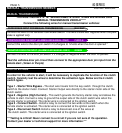
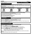
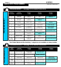
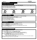
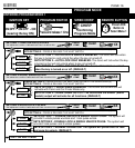
SYSTEM PROGRAMMING - Menu 1
SYSTEM PROGRAMMING - Menu 1
PAGE 12
PAGE 13
80 SERIES
80 SERIES
INSTALL MANUAL
INSTALL MANUAL
SYSTEM WIRING DETAILS
SYSTEM WIRING DETAILS
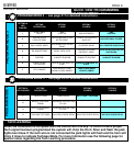
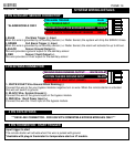
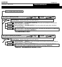
PARK BRAKE INPUT FOR MANUAL TRANSMISSIONS
YELLOW
BROWN
GRAY
RD/WHT
ORG/WHT
WHT/ORG
PINK
GRN/WHT
BLUE/WHT
BLUE
PURPLE
GREEN
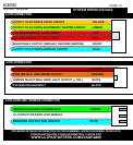
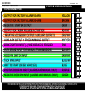
OUTPUT FOR FACTORY ALARM RE-ARM
OUTPUT FOR FACTORY ALARM DIS-ARM
NEGATIVE STARTER OUTPUT
OUTPUT FOR TRUNK RELEASE ACTIVATION
NEGATIVE ACCESSORY OUTPUT/ AUXILIARY OUTPUT 2
AUXILIARY OUTPUT 1/ PROGRAMMABLE OUTPUT
BRAKE SWITCH INPUT (+) WHEN BRAKE IS PRESSED
HOOD PIN SWITCH INPUT
TACH WIRE INPUT
WAIT TO START (DIESEL VEHICLES)
POSITIVE DOOR PIN INPUT (ALARMS AND MANUAL ONLY)
NEGATIVE DOOR PIN INPUT (ALARMS AND MANUAL ONLY)
FOR MORE DETAILED INFORMATION ON PROGRAMMING, WIRING DIAGRAMS, DOOR LOCK
CONFIGURATION AND OTHER INFORMATION, PLEASE VISIT
WWW.ULTRASTARTERS.COM/DIAGRAMS
BLK/WHT