


94-EN
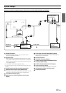
Connections
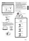
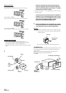
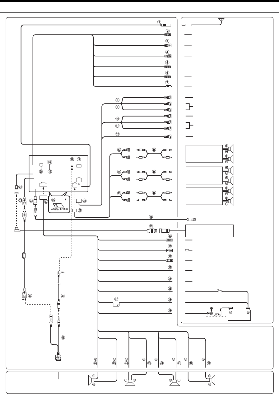
• Set the system switch to “NORM” when only a changer is connected (when the Ai-NET compatible equalizer is not used). When the IMPRINT
audio processor is connected, set to EQ/DIV position.
* The two system switches are located on the bottom of the unit.
CD Changer
(sold separately)
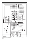
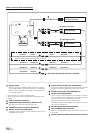
To remote output lead
To plus side of the back
lamp signal lead of the car
(White/Brown)
(Orange/White)
(White/Pink)
(Blue/White)
(Blue)
(Pink/Black)
(Yellow/Blue)
(Yellow)
(Black)
SPEAKER
LEFT
FRONT
(White/
Black)
SPEAKER
LEFT
REAR
(Green)
SPEAKER
RIGHT
REAR
(Violet/
Black)
SPEAKER
RIGHT
FRONT
(Gray)
To amplifier or equalizer
Front left
Rear left
Rear right Front right
REMOTE IN
REVERSE
M.CONT
REMOTE TURN-ON
POWER ANT
AUDIO INTERRUPT IN
PARKING BRAKE
BATTERY
GND
Antenna
(White)
(Green/
Black)
(Violet)
(Gray/
Black)
FOOT BRAKE
(Yellow/Black)
IGNITION
(Red)
To remote input lead
To power antenna
To vehicle phone
To the parking brake
signal lead
To the foot brake cord
or brake lamp cord
Battery
Speakers
Ignition key
(Yellow)
(Red)
(White)
(Yellow)
(Red)
(White)
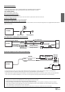
To BLUETOOTH INTERFACE
(KCE-400BT) (sold separately)
Amplifier
Amplifier
Amplifier
Rear Left
Rear Right
Front Left
Front Right
Subwoofers
To monitor control lead
To Audio Input terminals
(R, L)
To Audio Output terminals
(R, L)
To Video Input terminal
To Video Output terminal
To iPhone/iPod
To USB memory/
Portable audio player
To guide control input
terminal
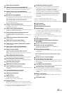
(White/Brown)
REMOTE OUT
or
GUIDE CONT
(White/Green)
GUIDE
(Black)
To steering remote control
interface box
To Guide Input terminal