


98-EN
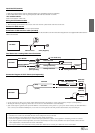
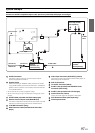
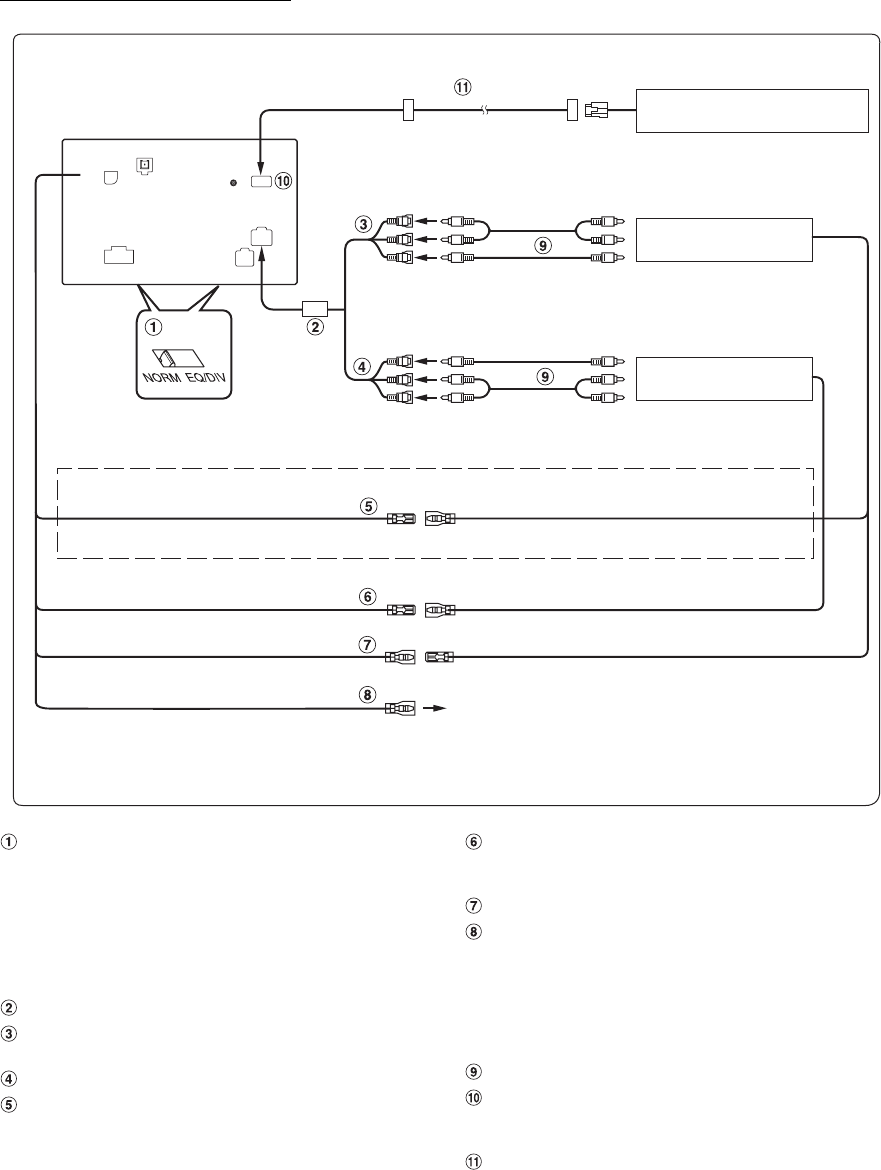
When Connecting External Equipment
To Audio Input terminal
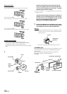
System Switch
When connecting an IMPRINT audio processor or divider
using Ai-NET feature, place the two switches in the EQ/DIV
position. When no device is connected, leave the switches
in the NORM position.
• Do not make the two switches to different settings.
• Be sure to turn the power off to the unit before changing the switch
position.
AUX I/O Camera In Connector
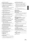
Video/Audio Output Connectors (AUX OUTPUT)
Use when connecting an optional monitor etc.
Video/Audio Input Connectors (AUX INPUT)
Monitor Control Lead (White/Pink)
Connect this to the Monitor Control Lead of the touch panel-
compatible rear monitor.
Remote Control Output Lead (White/Brown)
Connect this lead to the remote control input lead. This lead
outputs the controlling signals from the remote control.
Remote Control Input Lead (White/Brown)
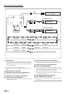
Reverse Lead (Orange/White)
Use only when a back-up camera is connected. Connect to
the plus side of the car’s reverse lamp. This lamp illuminates
when the transmission is shifted into reverse (R).
With this lead properly wired, the video picture
automatically switches to the back-up camera whenever the
car is put into reverse (R).
RCA Extension Cable (sold separately)
Direct CAMERA Input Connector
Use when the optional rearview camera HCE-C107D, etc. is
connected.
Camera extension cable (Included with Rear camera)
To Video Input terminal
To Audio Output terminal
Rearview camera HCE-C107D,
etc. (sold separately)
Rear monitor
(sold separately)
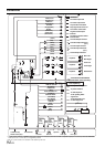
(White/Pink) M.CONT
M.CONT (White/Pink)
(White/Brown) REMOTE OUT REMOTE IN (White/Brown)
(White/Brown) REMOTE IN REMOTE OUT (White/Brown)
REVERSE
Use only when back-up camera is connected.
* Connect this to the touch panel-compatible rear monitor.
DVD Changer
(sold separately)
To Video Output terminal
(Orange/White)