M:\Product Information\366-348\Instructions\366-348 MGB Fuel Injection Installation Instructions_Grant_2.doc
366-348 Inst Fig 74
74.1
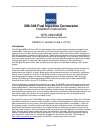
130. There is another pair of male spade terminals on the
fuse block immediately above the wires you just
connected. This position is labeled “5”. While the
outermost spade (74.1) is available on some MGBs, and
we know that it is used on the 80 MGB. This means that
the piggyback procedure we just went through (see
above) may have to be repeated on your car. A second
female spade to twin-male spade “piggyback” connector
(Moss 772-271) is supplied in the kit for this reason.
366-348 Inst Fig 76
76.1
76.2
131. Find the black wire with the brown 5 Amp inline fuse
(76.1) coming out of the fuel injection harness. Both
wires with inline fuses are black. It is the fuse that allows
us to tell them apart until the holder is marked.
132. Use the “Sharpie” black felt tip marker to label this
fuse holder “5”. By marking the fuse holder, we can tell
the black wires apart even if the fuses are removed.
133. Connect the female spade connector (76.2) to the
open male spade on the fuse block (see 74.1 above).
Again, if necessary, the piggyback procedure we just
went through (see above) will have to be repeated.
366-348 Inst Fig 77
77.1
77.2
134. Find the group of wires in the fuel injection harness
that are connected to the relay (77.1).
135. Secure the relay. You may use a spare screw (77.2)
found on the inner fender well as shown in Fig 77. If a
screw is not available, you may zip tie the metal relay
mounting plate to a convenient wiring bundle. Use a
location where the wires going to the relay are not under
any strain.
136. Find the supply of zip-ties supplied in the kit.
137. Loosely zip-tie the harness to secure it as you pick
the routing to protect the harness from being crushed,
melted, cut or abraded.
138. Feed any slack in the harness through the hole in
the firewall where the rectangular rubber plug was
removed.
This completes part 10 of the installation
Page 22 of 52