


8-37
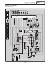
SIGNALING SYSTEM
ELEC
NO
YES NO
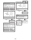
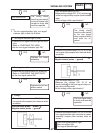
The wiring circuit
from the main switch
to the tail/brake light
coupler is faulty and
must be repaired.
This circuit is OK.
YES
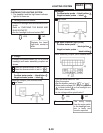
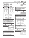
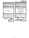
1. Turn signal indicator light (LEDs)
SCheck the turn signal indicator light for conti-
nuity.
Refer to “CHECKING THE LEDs”
SAre the turn signal indicator light OK?
Replace the meter
assembly.
EAS00799
3. The turn signal/position light, turn signal
indicator light or both fail to blink.
YES
2. Turn signal switch
SCheck the turn signal switch for continuity.
Refer to “CHECKING THE SWITCHES”.
SIs the turn signal switch OK?
Replace the left han-
dlebar switch.
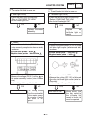
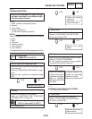
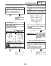
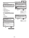
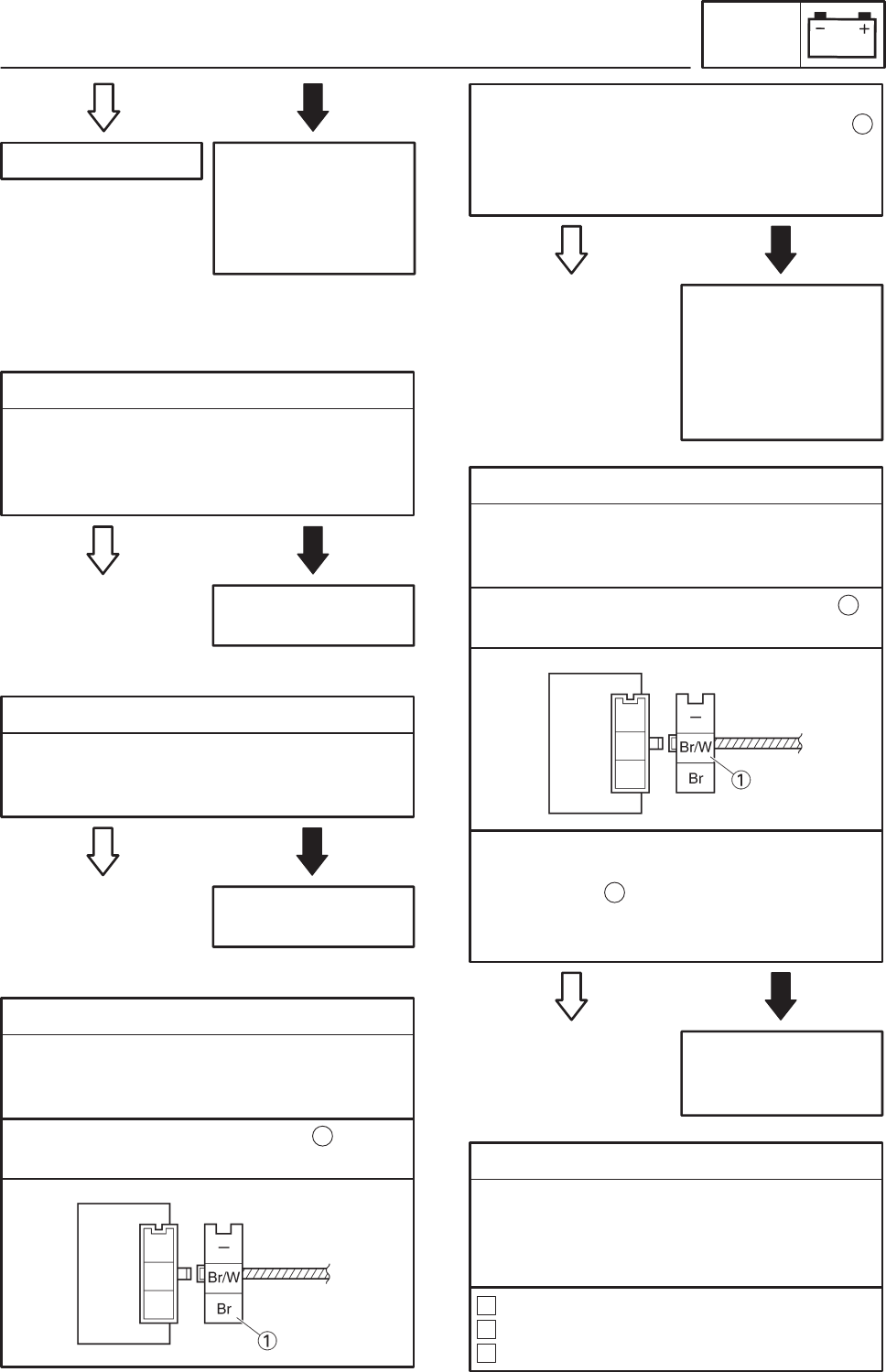
3. Voltage
SConnect the pocket tester (DC 20 V) to the
turn signal relay coupler (wire harness side)
as shown.
Positive tester probe ! brown
Negative tester probe ! ground
1
STurn the main switch to “ON”.
SMeasure the voltage (DC 12 V) on brown
at the turn signal relay coupler (wire harness
side).
SIs the voltage within specification?
1
YES NO
The wiring circuit
from the main switch
to the turn signal
relay coupler is faulty
and must be re-
paired.
YES NO
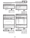
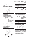
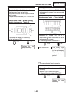
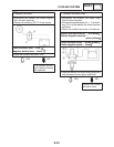
4. Voltage
SConnect the pocket tester (DC 20 V) to the
turn signal relay coupler (wire harness side)
as shown.
The turn signal relay
is faulty and must be
replaced.
Positive tester probe ! brown/white
Negative tester probe ! ground
1
STurn the main switch to “ON”.
SMeasure the voltage (DC 12 V) on
brown/white at the turn signal relay cou-
pler (wire harness side).
SIs the voltage within specification?
1
5. Voltage
SConnect the pocket tester (DC 20 V) to the
turn signal/position light connector or meter
assembly coupler (wire harness side) as
shown.
Front turn signal/position light
Rear turn signal light
Turn signal indicator light
A
B
C
NO