GB
3
OWNER'S MANUAL
•
C4
WELCOME TO THE WORLD
OF TUNTURI EXERCISING!
Your choice shows that you really want to invest
in your well being and condition; it also shows
you really value high quality and style. With
Tunturi Fitness Equipment, you’ve chosen a high
quality, safe and motivating product as your
training partner. Whatever your goal in training,
we are certain this is the training equipment
to get you there. You’ll fi nd information about
using your exercise equipment and what makes
for effi cient training at Tunturi’s website at
WWW.TUNTURI.COM.
ASSEMBLY
Start by unpacking the equipment. Two people are
needed for the assembly. Check that you have the
following parts:
1. Frame
2. Front support
3. Rear support
4. Front frame tube
5. Arms (2)
6. Footrests (2)
7. Meter
8. Handlebar
9. Shaft
10. Assembly kit (contents marked with * in the
spare part list): keep the assembly tools, as you may
need them e.g. for adjusting the equipment
If necessary, please contact your dealer with the
model, equipment serial no. and spare part no.
of the missing part. You’ll fi nd a spare part list at
the back of this guide. The packaging includes a
silicate bag for absorbing moisture during storage
and transportation. Please dispose of the bag once
you have unpacked the equipment. The directions
left, right, front and back are defi ned as seen from
the exercising position. Allow at least 100 cm of
clearance around the equipment.
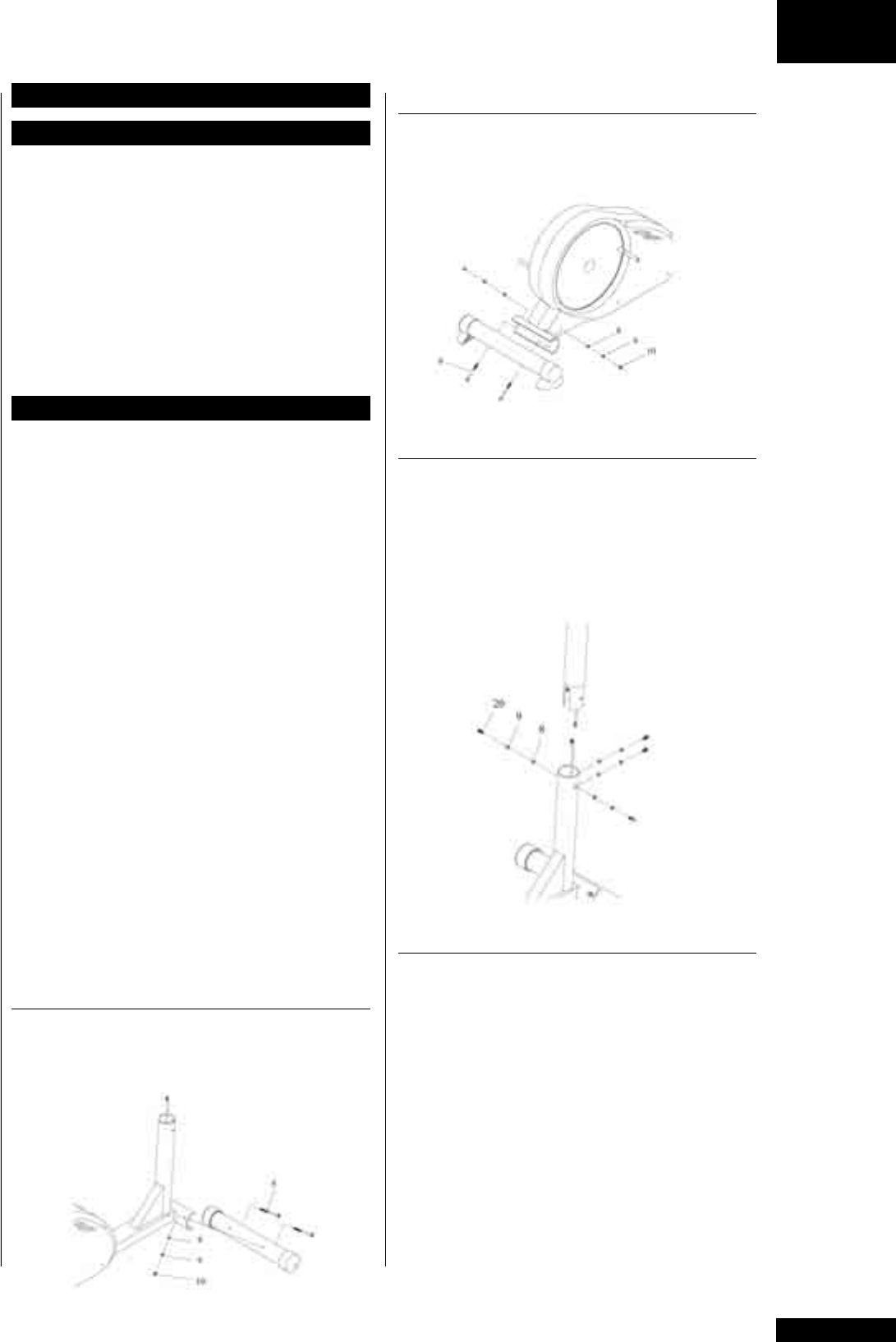
FRONT SUPPORT
Attach the front support with transportation
wheels to the main frame with two bolts, washers,
locking sleeves and nuts.
REAR SUPPORT
Push the stand feet to the rear support ends and
attach the rear support to the main frame with two
bolts, washers, locking sleeves and nuts.
FRONT FRAME TUBE
Remove the rubber band from around meter cable
coming from the frame tube. Attach the meter
cable to the connector coming from the front
frame tube. Push the front frame tube inside the
frame tube: do not damage the meter cable! Attach
the front frame tube tight to the frame with the
washers and attachment screws.
ARMS
Push the metal shaft through the bracket housing
of the left arm. Attach now the left arm to the
front frame tube by pushing the metal shaft
through the opening in the tube. Push the right
arm on the shaft and lock it by tightening a large
washer, a locking sleeve and a screw to the both
ends of the shaft. Tighten the arms using two Allen
keys. Push the left footrest support forward so that
you can push the adjustment tube in the front of
the foot rest support inside the arm tube. Select the
appropriate adjustment (see Adjusting the footrest
supports) and lock the adjustment tube with the
locking screw. Repeat the procedure with the right
footrest support.


