


58
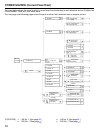
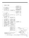
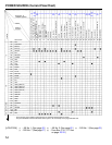
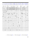
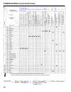
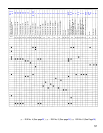
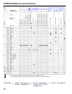
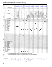
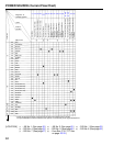
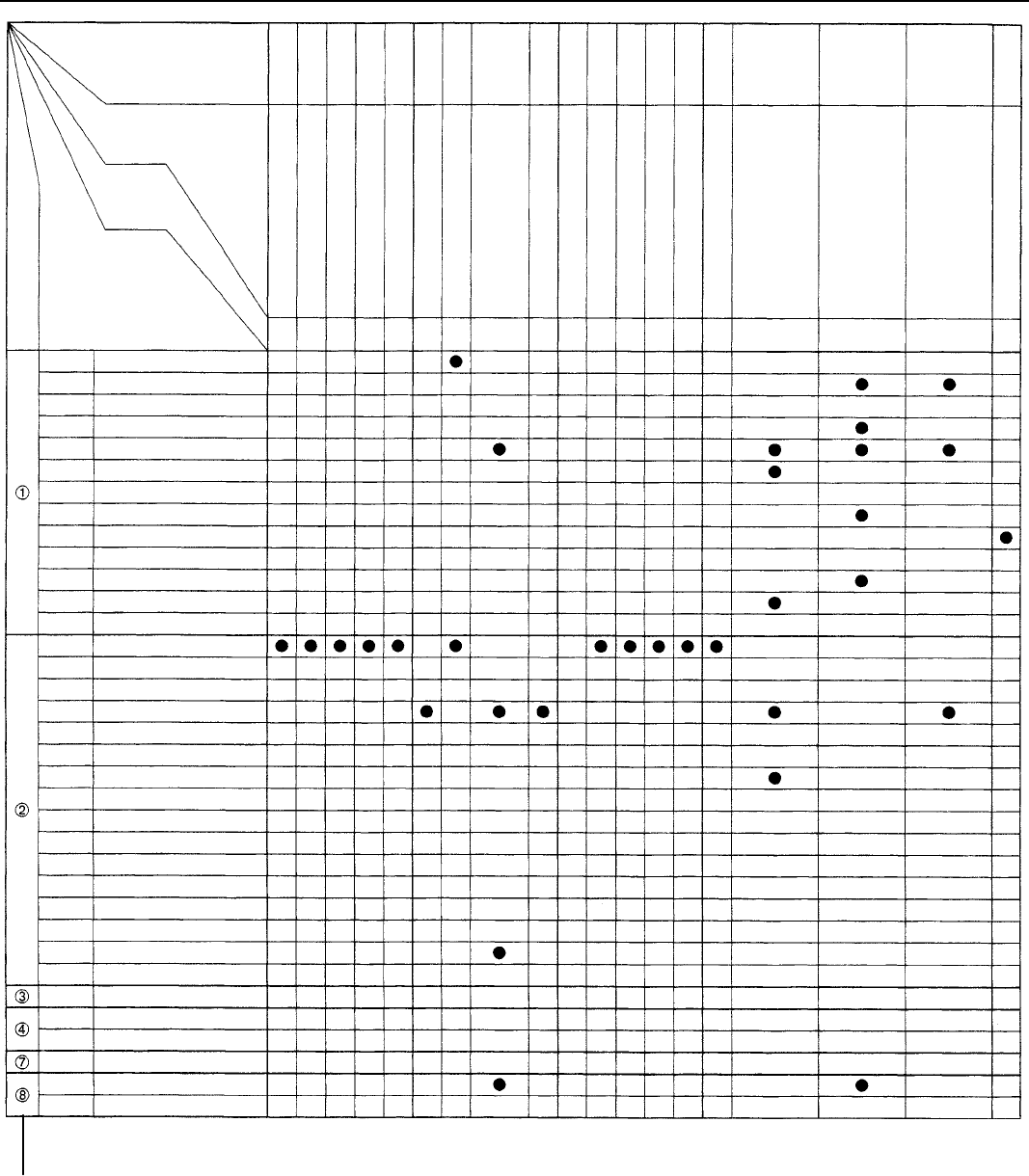
POWER SOURCE (Current Flow Chart)
*Page Nos. of
Related Systems
Parts
Code or
Location
CB or Fuse
Location
* These are the page numbers of the first page on which the related system is shown.
The part indicated is located somewhere in the system, not necessarily on the page indicated here.
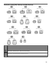
B
I5 I6 I7 I8 I9 I11 I12
I13
I14 I16 I17 I18
I19
80
68
72
80
130
134
138
140
106
120
130
144
76
114
130
170
214
246
177
Injector No. 2
Injector No. 3
Injector No. 4
Injector No. 5 (1MZ–FE)
Injector No. 6 (1MZ–FE)
Injector Key Cylinder Light
Ignition SW and Unlock Warning
SW
Integration Relay
Interior Light
Ignition Coil No. 1 (1MZ–FE)
Ignition Coil No. 2 (1MZ–FE)
Ignition Coil No. 3 (1MZ–FE)
Ignition Coil No. 4 (1MZ–FE)
40A AM1
15A CIG/RADIO
40A DEFOG
15A ECU–1G
10A GAUGE
7.5A IGN
10A MIR–HTR
30A POWER
7.5A SRS
15A STOP
15A TAIL
7.5A TURN
20A WIPER
30A AM2
7.5A ALT–S
30A CDS FAN
20A DOME
15A ECU–B
15A EFI
10A HAZ
15A HEAD (LWR–LH)
15A HEAD (LWR–RH)
15A HEAD (UPR–LH)
15A HEAD (UPR–RH)
15A HEAD LH
15A HEAD RH
10A HORN
40A MAIN
7.5A OBD
10A STARTER
10A A/C
40A HEATER
7.5A DRL
100A ALT
60A ABS
Ignition Coil No. 5 (1MZ–FE)
Ignition Coil No. 6 (1MZ–FE)
Junction Connector
Junction Connector
Junction Connector
Junction Connector (for Airbag
System)
I20 I21 J1 J2 J3 J4
80 80 80 80
112
126
140
170
68
80
68
80
68
80
68
80
68
80
68
80
90
118
134
192
224
252
98
120
138
210
80
154
182
190
204
126
156
189
198
236
130
156
182
214
226
234
134
160
198
222
228
236
154
168
204
224
230
130
134
138
140
130
134
138
140
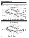
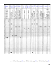
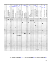
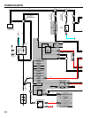
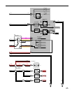
[LOCATION] (1)
(7)
: J/B No. 1 (See page 20)
: R/B No. 7 (See page )
(2)
(8)
: J/B No. 2 (See page 19)
: Fuse Box (F10, F17 See
on page )
(3) : R/B No. 1 (See page 23)
20
22
25
27
28 29