


54
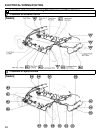
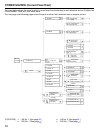
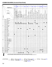
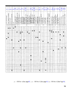
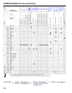
POWER SOURCE (Current Flow Chart)
40A AM1
15A CIG/RADIO
40A DEFOG
15A ECU–1G
10A GAUGE
7.5A IGN
10A MIR–HTR
30A POWER
7.5A SRS
15A STOP
15A TAIL
7.5A TURN
20A WIPER
30A AM2
7.5A ALT–S
30A CDS FAN
20A DOME
15A ECU–B
15A EFI
10A HAZ
15A HEAD (LWR–LH)
15A HEAD (LWR–RH)
15A HEAD (UPR–LH)
15A HEAD (UPR–RH)
15A HEAD LH
15A HEAD RH
10A HORN
40A MAIN
7.5A OBD
10A STARTER
10A A/C
40A HEATER
7.5A DRL
100A ALT
60A ABS
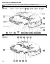
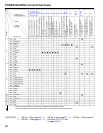
A/C Condenser Fan Motor (5S–FE)
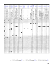
242
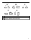
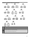
A4 A5 A11A1
*Page Nos. of
Related Systems
Parts
Code or
Location
CB or Fuse
Location
A2 A3
* These are the page numbers of the first page on which the related system is shown.
The part indicated is located somewhere in the system, not necessarily on the page indicated here.
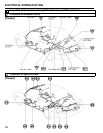
B
A12A6 A7 A13 A17 A18A14 A16 A21 B1 B2 B3 B4 B5 B6 B7 B9 B10
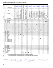
214 252
126
252
210 210 246
246
252
126
222
224
152 236 166
246
252
246
252
126
246
252
160
166
220 220
A/C Triple Pressure SW (A/C Dual
and Single Pressure SW)
A/C Magnetic Clutch and Lock
Sensor
ABS Actuator and ECU
(TMM Made)
ABS Actuator (TMC Made)
ABS Actuator and ECU
(TMM Made)
ABS Relay
A/C Amplifier
A/C SW
ABS ECU (TMC Made)
Air Inlet Control Servo Motor
Air Vent Mode Control Servo Motor
Ashtray Illumination
Auto Antenna Motor and Relay
Back–Up Light SW (M/T)
Brake Fluid Level SW
Back Door Lock Control SW
Blower Motor
Blower Resistor
Blower SW
Buckle SW LH
Back Door Lock Motor (W/G)
Buckle SW RH
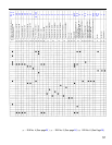
A10
246
252
210210210214
246
252
242
246
252
ABS ECU (TMC Made)
A/C Evaporator Temp. Sensor
ABS Relay
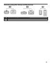
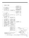
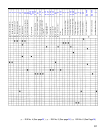
[LOCATION] (1)
(7)
: J/B No. 1 (See page 20)
: R/B No. 7 (See page )
(2)
(8)
: J/B No. 2 (See page 19)
: Fuse Box (F10, F17 See
on page )
(3) : R/B No. 1 (See page 23)
20
22
25
27
28 29