


174
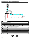
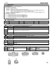
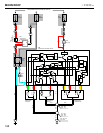
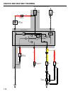
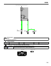
SRS (SUPPLEMENTAL RESTRAINT SYSTEM)
NOTICE: When inspecting or repairing the SRS (supplemental restraint system), perform the operation in
accordance with the following precautionary instructions and the procedure and precautions in the Repair
Manual for the applicable model year.
B Malfunction symptoms of the supplemental restraint system are difficult to confirm, so the diagnostic trouble
codes become the most important source of information when troubleshooting.
When troubleshooting the supplemental restraint system, always inspect the diagnostic trouble codes before
disconnecting the battery.
B Work must be started after 90 seconds from the time the Ignition SW is set to the “LOCK” position and the
negative (–) terminal cable is disconnected from the battery.
(The supplemental restraint system is equipped with a back–up power source so that if work is started within
90 seconds of disconnecting the negative (–) terminal cable of the battery, the SRS may be activated.)
When the negative (–) terminal cable is disconnected from the battery, memory of the clock and audio systems
will be cancelled. So before starting work, make a record of the contents momorized by each memory system.
When work is finished, reset the clock and audio system as before and adjust the clock. This vehicle has tilt
and telescopic steering, power seat and outside rear view mirror and power shoulder belt anchorage, which
are all equipped with memory function, it is not possible to make a record of the customer, and ask the
customer to adjust the features and reset the memory.
To avoid erasing the memory of each memory system, never use a back–up power supply from outside the
vehicle.
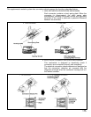
B When removing the steering wheel pad or handling a new steering wheel pad, keep the pad upper surface
facing upward. Also, lock the lock lever of the twin lock type connector at the rear of the pad and take care
not to damage the connector.
(Storing the pad with its metallic surface up may lead to a serious accident if the SRS inflates for some reason.)
B Store the steering wheel pad where the ambient temperature remains below 93°C (200°F), without high
humidity and away from electrical noise.
B Never use SRS parts from another vehicle. When replacing SRS parts, replace them with new parts.
B Never disassemble and repair the steering wheel pad, center SRS sensor assembly or front airbag sensors.
B Before repairing the body, remove the airbag sensors if during repair shocks are likely to be applied to the
sensors due to vibration of the body or direct tapping with tools or other parts.
B Do not reuse a steering wheel pad or front airbag sensors.
After evaluating whether the center airbag sensor assembly is damaged or not, decide whether or not to reuse
it. (See the Repair Manual for the method for evaluating the center airbag sensor assembly.)
B When troubleshooting the supplemental restraint system, use a high–impedance (Min. 10k/V) tester.
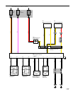
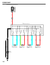
B The wire harness of the supplemental restraint system is integrated with the cowl wire harness assembly and
engine wire harness assembly.
The vehicle wiring harness exclusively for the airbag system is distinguished by corrugated yellow tubing, as
are the connectors.
B Do not measure the resistance of the airbag squib.
(It is possible this will deploy the airbag and is very dangerous.)
B If the wire harness used in the supplemental restraint system is damaged, replace the whole wire harness
assembly.
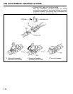
When the connector to the airbag front sensors can be repaired alone (when there is no damage to the wire
harness), use the repair wire specially designed for the purpose.
(Refer to the Repair Manual for the applicable Model year for details of the replacement method.)
B INFORMATION LABELS (NOTICES) are attached to the periphery of the SRS components. Follow the
instructions on the notices.