


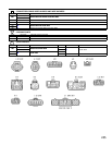
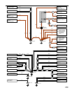
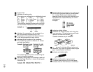
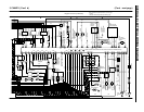
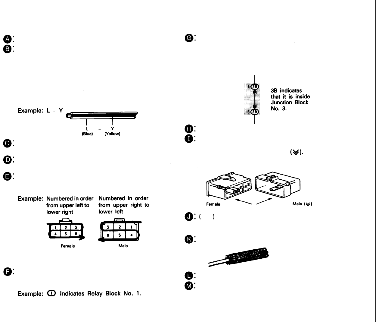
Junction Block (The number in the circle is the
J/B No. and connector code is shown beside
it). Junction Blocks are shaded to clearly
separate them from other parts (different junc-
tion blocks are shaded differently for further
clarification.).
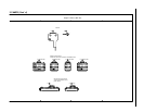
Example:
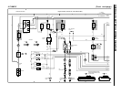
Indicates related system.
Indicates the wiring harness and wiring har-
ness connector. The wiring harness with male
terminal is shown with arrows
Outside numerals are pin numbers.
is used to indicate different wiring and
connector, etc. when the vehicle model, engine
type, or specification is different.
Indicates a shielded cable.
Indicates and located on ground point.
The same code occuring on the next page
indicates that the wire harness is continuous.
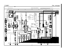
System Title
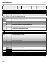
Indicates the wiring color.
Wire colors are indicated by an alphabetical code.
B = Black L = Blue R = Red
BR = Brown LG= Light Green V = Violet
G = Green O = Orange W = White
GR= Gray P = Pink Y = Yellow
The first letter indicates the basic wire color and
the second letter indicates the color of the stripe.
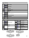
Indicates the connector to be connected to a
part (the numeral indicates the pin No.)
The position of the parts is the same as shown
in the wiring diagram and wire routing.
Indicates the pin number of the connector.
The numbering system is different for female
and male connectors.
The numbering system for the overall wiring dia-
gram is the same as above.
Indicates a Relay Block. No Shading is used and
only the Relay Block No. is shown to distinguish
it from the J/B.
263